


12
Use this setting to choose one of three color temperature presets:
• D55 (5500K)
• D65 (6500K)
• 9300K
• USER (Adjustable Color Bias and Gain)
• Linear (No processing is applied to the panel)
Use this setting to enable monochrome mode. Only the luminance of the image will be displayed as a grayscale picture.
■
Gamma
Use this setting to choose one of four selectable Gamma tables:
• 1.6
• 1.8
• 2.0
• 2.2
• 2.4
Note: Gamma is disabled when
Color Temperature
is set to
Linear
■
RGB Bias and Gain
Select this submenu to fine-tune the monitor’s color balance (R, G, B). This should only be done by someone experienced
with video engineering, as this will alter the overall color shading of the screen. The purpose is to allow color matching to
other types of monitors and/or displays. Note: The Color Temperature preset will automatically switch to USER when Color
Bias settings are adjusted. It is normal for color bias adjustments to be very subtle.
When selecting the RGB Bias and Gain submenu, gain adjustment indicators will appear at the top of the screen, and bias
adjustment indicators will appear at the bottom of the screen:
Use the
▲
and
▼
buttons to select each individual bias or gain control. Press SELECT to begin adjusting the control. Use the
▲
and
▼
buttons to increase or decrease the value.
Alternately, the image adjustment buttons (Brightness, Color, Tint, Contrast) can be used to easily adjust the bias and gain
settings as shown below. The buttons affect whichever row of controls (gain or bias) is currently selected.
■
Check Field
Use the check field modes for monitor calibration or to analyze individual color components of an image. In Monochrome
mode, all color is disabled and only a grayscale image is shown. In Blue, Green, and Red check field modes, only the selected
color will be shown.
RGB Bias and Gain
17
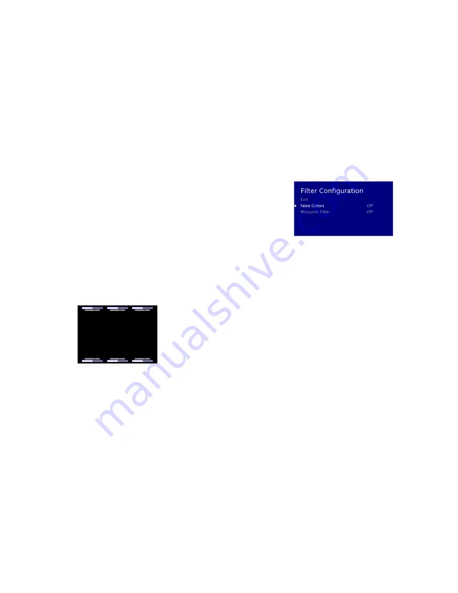
FILTER CONFIGURATION SUBMENU
■
False Colors
This monitor has a false color filter to aid in the setting of camera exposure. As the camera Iris is adjusted, elements of the
image will change color based on the luminance or brightness values. This enables proper exposure to be achieved without
the use of costly, complicated external equipment. To best utilize this feature, you must understand the color chart below
and have a basic understanding of camera exposure. Normally, when shooting subjects like people, it is common practice to
set exposure of faces to the equivalent of approximately 56 IRE. The false color filter will show this area as the color PINK on
the monitor. Therefore, as you increase exposure (open the IRIS), your subject will change color as indicated on the chart:
PINK, then GREY, then a few shades of YELLOW. Over exposed subjects (above 101 IRE) on the monitor will be shown as RED.
In addition, underexposed subjects will show as DEEP-BLUE to DARK–BLUE, with clipped-blacks indicated with a FUCHSIA-like
color. Lastly, the color GREEN is used to indicate elements of the image that are approximately 45 IRE. This represents a
‘neutral’ or ‘mid-level’ exposure commonly used for objects (not people).


