


22
■
Text Tally
Use the Text Tally option to lock the Text String color to the same color as the current Tally color. When there is no specific
tally color enabled, the text string will default to the Text Color selection made in the IMD & Tally Configuration menu option.
SYSTEM INFORMATION SUBMENU
■
System
This shows the System firmware version of your monitor.
■
Power Module
This shows the Power Module firmware version of your monitor.
■
Keypad
This shows the Keypad firmware version of your monitor.
■
Slot (1 or 2)
This shows your module type and the firmware version of your module. If no module is present, the word EMPTY will appear
in parentheses.
7
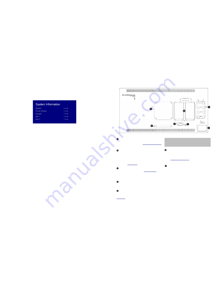
Rear Panel Features
YPbPr and CVBS Video Input and Output
The V-MD151 has CVBS and YPbPr inputs and one active loop-
through output for each input. See
Compatible Input Formats
for details on accepted formats.
Power Input
Connect 12VDC to the 4-pin XLR power input connector.
Power should only be supplied from the included power
supply.
IMPORTANT: If using a power source other than the included
power supply, damage may result. Please use the pin out
diagram in the
Specifications
section.
Tally Input Connector
The LED tally can be activated via the
HD-15 connector
by
connecting the corresponding pin to ground. A variety of
external devices can be used to perform the contact closure.
No additional power should be supplied to the HD-15 port.
Desktop Mounting Holes
These holes are used when attaching the monitor to the
optional desktop stand.
VESA 75mm Hole Pattern
VESA-standard 75 mm hole-patterns is provided to
accommodate a variety of custom mounting options. See
Dimensions
for further details.
Warning:
Please use only the square type VESA mount (which
fits inside the VESA Screw Length WARNING silkscreen) with
the 75mm hole pattern in order to avoid obstructing Module
Slot 2.
Optional Module Slot 1 / Slot 2
The V-MD monitor comes with Module Slots for Marshall
Electronics’ line of future proof Input Modules. Please contact
Marshall Electronics for a list of compatible Input Modules.
See the
Input Module Installation
instructions for details on
Module installation.
PROG Port
The PROG port is a Service / Upgrade port only. Please
contact Marshall Electronics for more information.


