


QUI-1057
Page 16
Markes International Ltd
T:
+44 (0)1443 230935
F:
+44 (0)1443 231531
E:
www.markes.com
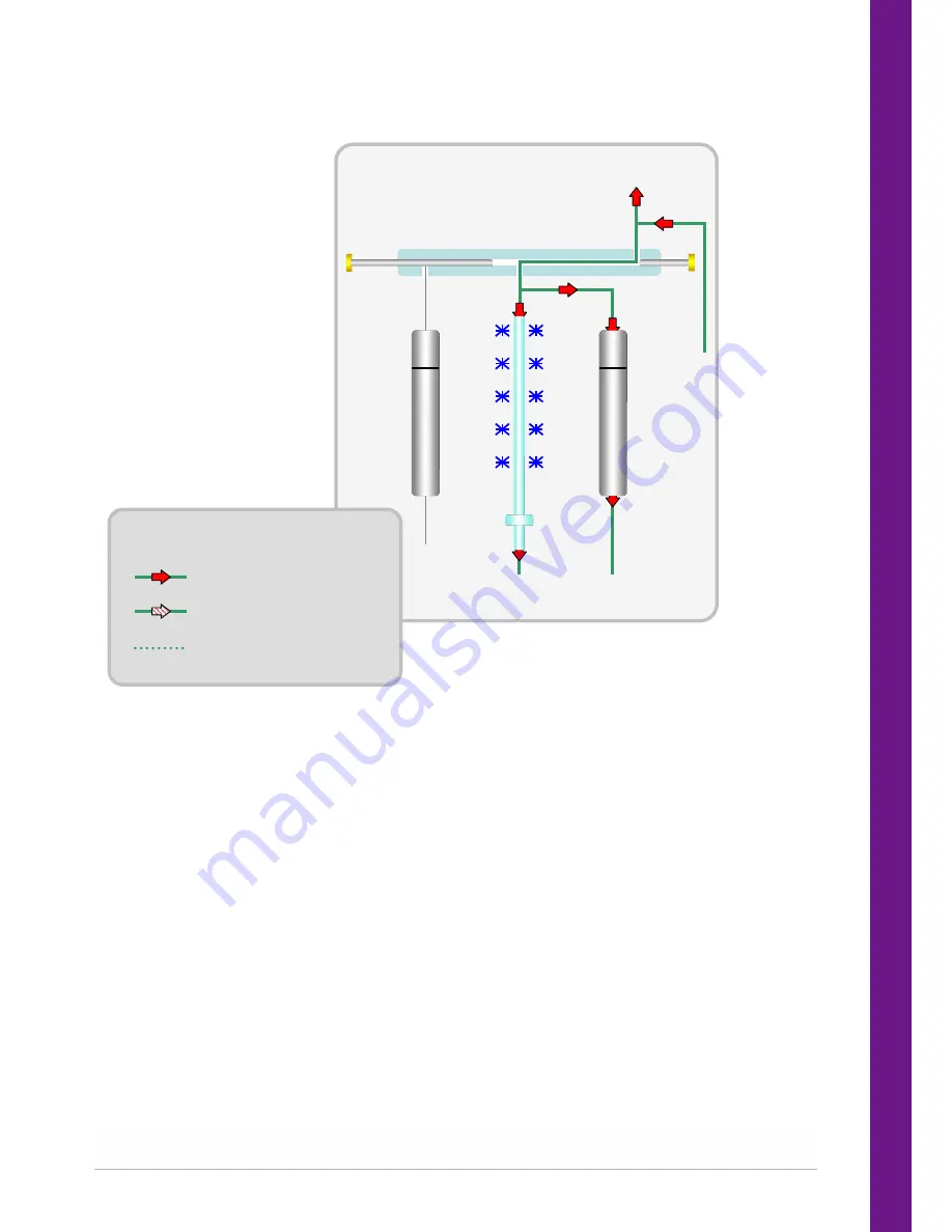
2.2.5
Pre trap fire purge
Sampl
e
Tu
be
Spli
t T
ube
Col
d
Tra
p
GC
Heated Valve
Pressure and flow
Pressure (flow optional)
Pressure, no flow
KEY
Following primary desorption, the heated valve is moved and carrier gas is flushed through the split tube
and the trap to remove any residual air and water prior to trap injection. It may also be used to dry purge
the cold trap prior to injection when direct desorbing solid or humid samples.
This pre-trap fire purge time can be adjusted in the TD method.


