background image

Series E Ergonomics Force Gauges 


User’s Guide 


4


2   POWER 


The gauge is powered either by an 8.4V NiMH rechargeable battery or by an AC adapter. Since the 
batteries are subject to self discharge, it may be necessary to recharge the unit after a prolonged period 
of storage. Plug the accompanying charger into the AC outlet and insert the charger plug into the 
receptacle on the gauge (refer to the illustration below). The battery will fully charge in approximately 8 
hours.  


Caution!


Do not use chargers or batteries other than supplied or instrument damage may occur. 

If the AC adapter is plugged in, an icon appears in the lower left corner of the display, as follows: 


If the AC adapter is not plugged in, battery power drainage is denoted in a five-step process: 
 

Battery Life: 

>75% 50 

– 75% 

25 – 50% 

<25% 

<2% 

Indicator: 


 (flashing) 

 
At a critically low level, a message appears, “BATTERY VOLTAGE TOO LOW. POWERING OFF”. An 
audio tone will sound and the gauge will power off. 
 
The gauge can be configured to automatically power off following a period of inactivity. Refer to the 

Other 

Settings

 section for details.   

 
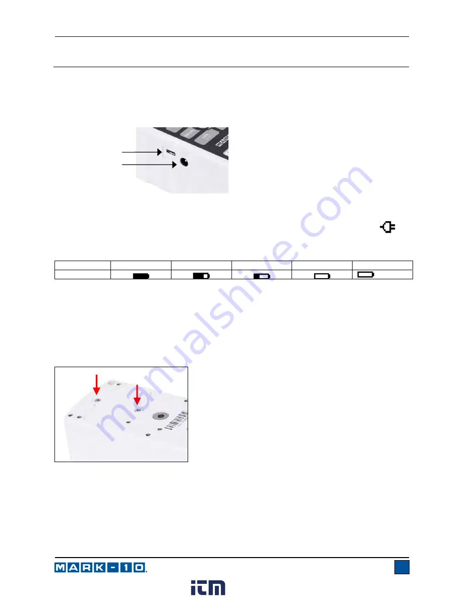
If battery replacement is necessary, it can be accessed by removing the battery cover in the rear of the 
housing with two screws, as shown below:  


USB connector 

Power input jack 

www.

.com

[email protected]

1.800.561.8187

Summary of Contents for ME-100

Page 1: ...Series E ERGONOMICS FORCE GAUGES User s Guide www com information itm com 1 800 561 8187...

Page 2: ...des setup safety and operation instructions Dimensions and specifications are also provided For additional information or answers to your questions please do not hesitate to contact us Our technical s...

Page 3: ...ite software MESURTM gauge software 90 day trial User s Guide 1 E1003 Padded attachment rectangular 1 E1004 Padded attachment curved 1 E1006 Hook 1 E1009 Double handle grip 1 E1000 Carrying case small...

Page 4: ...rically conductive liquids at all times 3 The gauge should be serviced by a trained technician only AC power must be disconnected and the gauge must be powered off before the housing is opened 4 Alway...

Page 5: ...ge may occur If the AC adapter is plugged in an icon appears in the lower left corner of the display as follows If the AC adapter is not plugged in battery power drainage is denoted in a five step pro...

Page 6: ...ent pull back on the lever in the rear of the housing as shown below If the E1011 grip adapter pictured below is used common grips and attachments may be mounted via the integrated 5 16 18F thread 3 1...

Page 7: ...oses Failure to use a dowel pin properly can result in a hazardous situation 3 2 Installing the USB driver Caution Install the USB driver before physically connecting the gauge to a PC with the USB ca...

Page 8: ...overload condition is imminent The bar increases either to the right or to the left from the midpoint of the graph Increasing to the right indicates compression load increasing to the left indicates...

Page 9: ...es between tension and compression directions while configuring set points and other menu items ZERO Zeroes the primary reading and peaks UP Navigates up through the menu and sub menus MENU Enters the...

Page 10: ...rs as follows One two or none of the set points may be enabled To toggle between the tension and compression directions press the DIRECTION key If two set points have been enabled they are displayed i...

Page 11: ...the live measured reading 6 2 Peak Compression PC The primary reading corresponds to the peak compression reading observed If the actual force decreases from the peak value the peak will still be ret...

Page 12: ...0 1 sec increments Averaging Time The time duration of the averaging sequence This setting is ignored when Stop at Force is enabled unless the 300 sec limit is reached Available settings 0 1 300 0 sec...

Page 13: ...able as shown below 6 5 3 Stop Condition Data capture is automatically terminated when the Stop Condition has been reached Several conditions are available as shown below Function Description Enabled...

Page 14: ...orage and press ENTER Then exit the menu In the home screen the data record number 0000 appears below the primary reading Press DATA at any time to save the displayed reading The record number will in...

Page 15: ...ress ENTER to output data and statistics to an external device The display will show SENDING DATA then SENDING STATS then DATA SENT then STATS SENT If there was a problem with communication the displa...

Page 16: ...baud rate as required for the application It must be set to the same value as the receiving device 8 1 2 Data Format Select the desired data format The display appears as follows Selection Description...

Page 17: ...e decimal point is dependent of the gauge s resolution Any detected errors are reported back by means of error code 10 illegal command 8 2 DATA Key Functions The DATA key can be configured to perform...

Page 18: ...ads in each direction 3 To escape the Calibration menu at any time press ESCAPE The display appears as follows Selecting Cancel will revert back to the Calibration setup Selecting Exit w o saving will...

Page 19: ...ss ENTER 8 The display appears as follows Apply a weight equal to the full scale of the instrument then press ENTER 9 After displaying Please wait the display appears as follows CALIBRATION COMPRESSIO...

Page 20: ...pression calibration points have been completed the display appears as follows Press ENTER 12 The display appears as follows Reverse the orientation of the load cell shaft by rotating the gauge 180 de...

Page 21: ...oad is not swinging oscillating or vibrating in any manner Then try again The calibration weight does not match the set value The entered calibration point is too close to the previous point CALIBRATI...

Page 22: ...ry time the MENU key is selected a password must be provided Select Menu Key from the sub menu Follow the same procedure as described above 10 3 Locking Out Other Keys Other keys may be locked out ind...

Page 23: ...00 counts or less To access these settings select Automatic Shutoff from the menu The display appears as follows Selection Description Disabled Disable automatic shutoff Enabled Enable automatic shuto...

Page 24: ...ss ENTER to modify the contrast Select a value from 0 to 25 25 producing the most contrast 11 4 Tones Audible tones can be enabled for all key presses and alerts such as overload set point value reach...

Page 25: ...ght on up to 7 hours of continuous use Backlight off up to 24 hours of continuous use Measurement units lbF ozF gF kgF N kN depending on model USB output Configurable up to 115 200 baud Safe overload...

Page 26: ...Settings All disabled Tones Keys Enabled Alerts Enabled Set Points Momentary Automatic Shutoff Enabled Set Minutes 5 Backlight Auto Set Minutes 1 Initial Settings Units lbF Mode Real Time Passwords A...

Reviews: