background image


20 


OSD FUNCTIONS


The  OSD  settings  highlighted  in  green  are  the  preferred  settings.  See  the  shipped  OSD 

configuration in the APPENDIX. 


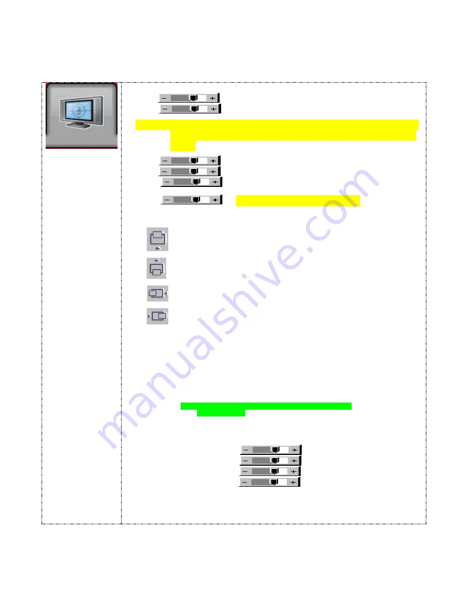
Picture : 

Brightness  


Increase/decrease panel brightness level, total: 100 steps  

Contrast      


Increase/decrease panel contrast level, total: 100 steps


NOTE:  Use of the Brightness or Contrast controls may inhibit visibility 

of ECDIS information, particularly when using the night color 

tables.


Saturation   

         Increase/decrease saturation, total: 100 steps


Hue **         

         Increase/decrease Hue level, total: 100 steps 

Sharpness*  

        Increase/decrease sharpness, total: 30 steps 

 
Backlight      


(OSD CONTROL DISABLED)


Position

#


Aspect / Size 


                              - Fill Screen : Enable full screen expansion for lower resolution Image 

              - Fill to Aspect Ratio: Enable fill screen expansion for lower resolution      

                                image according to aspect ratio  

                              - 4 : 3 : scaling format in 4:3 

                              - 16 : 9  : scaling format in 16:9 

                              - 16 : 10  : scaling format in 16:10 

                              - 2.35 : 1  : scaling format in 2.35:1 

                              - 2 : 1 : scaling format in 2:1 

                              - 1 : 1 : Display the exact image resolution on the screen without   

                                          image expansion. 

                              - Custom Sizing

##

 :  

-


Overscan 

-


Normal  

-


Custom 


                       H Size 


                       V Size 


                       H Pan 


                       V Pan 


* : DISPLAY IN VIDEO MODE ONLY 

** : FUNCTION IN ARGB/ DVI / VIDEO NTSC MODE ONLY 

# : FUNCTION IN ARGB MODE ONLY 

## : DISPLAY IN VIDEO MODE ONLY  


Move the image position upward


Move the image position downward 

Move the image position to the left 

Move the image position to the right 

Summary of Contents for MPC-MI19

Page 1: ...USER MANUAL 19 Bridge Display Type Approved by ABS N S E W MARINE PC MARINE PC ...

Page 2: ...nability to use MarinePC s product or its documentation even if advised of the possibility of such damages Endorsement Product names mentioned herein are used for identification purposes only and may be trademarks and or registered trade marks of their respective companies Copyright This document contains proprietary information protected by copyright All rights are reserved No part of this manual...

Page 3: ...EL CAUTION RISK OF ELECTRIC SHOCK DO NOT OPEN CAUTION TO REDUCE THE RISK OF ELECTRIC SHOCK DO NOT REMOVE COVER OR BACK NO USER SERVICEABLE PARTS INSIDE REFER SERVICING TO QUALIFIED SERVICE PERSONNEL This symbol warns the user that un insulated voltage within the unit may be large enough to cause electric shock Therefore it is dangerous to touch any part inside the unit This symbol alerts the user ...

Page 4: ...M BUZZER 14 Remote Brightness Interface Male Connector REMOTE BRIGHTNESS 15 Programming Field Service Interface PROG 15 Earth Ground 15 CABLE TIEDOWNS 15 Compass Safe Distance 16 ECDIS Installation Setup 16 OPERATION 17 FRONT PANEL DISPLAY USER CONTROLS 17 Power ON OFF 17 OSD CONTROL BUTTONS 17 OSD HOT KEYS 18 FRONT PANEL Backlight Dimming Control 18 FRONT PANEL INDICATORS 18 FRONT PANEL ALARMS 19...

Page 5: ...t Brightness Minimum Value Command BRI INPUT 39 Backlight Brightness Maximum Value Command BRM INPUT 39 Backlight Brightness Command BRT INPUT 39 BZZ INPUT 40 Download ECDIS DVI D Table from Display Command DND INPUT 40 Download ECDIS VGA Table from Display Command DNV INPUT 41 Read ECDIS Table Number of Pages Command CMD INPUT 41 Elapsed Time Counter Command ETC INPUT 42 Request Manufacturer ID M...

Page 6: ...ble kits are available separately Please check the carton and its content for damage that may have occurred during shipment Report any damage to the shipping agent immediately and do not operate the display if it appears to have been damaged All warranty returns must use the original shipping carton and packaging materials to prevent shipping damage Report any damage to the shipping agent immediat...

Page 7: ...as well as recreational users MarinePC is based in Phoenix Arizona USA This product is designed manufactured and tested in the United States and is certified compliant with the IMO Standard IEC60945 for Maritime Bridge Electronics by the American Bureau of Shipping ABS MarinePC offers a full range of marinized LCD Displays and Computers from our outdoor waterproof 8 4 10 4 12 1 and 15 MPC AWM Prof...

Page 8: ...ical shock unplug the display from the power source before relocating This display should be operated from the type of power source indicated on the displays rating label Do not place any heavy objects on the power cord Damage to the cord may cause shock or fire Unplug this displays power source and refer servicing to qualified service personnel in the event that Power cord or plug is damaged or f...

Page 9: ...Hertz IAW In Accordance With IHO International Hydrographic Organization kHz Kilohertz LCD Liquid Crystal Display LED Light Emitting Diode NAK Negative Acknowledge NTE Not To Exceed OSD On Screen Display PBP Picture By Picture PIP Picture In Picture RX Receive RGB Red Green Blue video SCOM Serial Communication interface TX Transmit VAC Volts Alternating Current VDC Volts Direct Current VESA Video ...

Page 10: ...s focus with no geometric distortion Auto Screen size adjustment Will adjust display for optional performance and provide full screen images on even non native formats Wide viewing angle 89 typical all directions Anti Reflective Screen All models are supplied with Anti reflective Anti glare protective safety glass Low power consumption ...

Page 11: ...e of the device See the safe compass distance later in this section The maximum cable lengths must not exceed the recommended industry recommended lengths The display must be properly grounded A short wide cable braid gives the best results For ECDIS applications the calculated nominal recommended viewing distance is 1 013 mm IEC62288 Part 7 5 Screen resolution Mounting Instructions The display ca...

Page 12: ... back shell are available separately For installation follow the following procedure 1 Select the smallest compression insert that will fit over the DC power wires 2 Insert the wires through the compression insert NOTE Wires must be properly sized to support the current related to the input voltage being used and the length of the wires 3 Solder the contacts to the 24 VDC wire and the 24 VDC retur...

Page 13: ...in male connector and secure the cable with the two jack screws The input voltage is 24 VDC nominal 9 32 VDC is supported Mating DC power connection kit is available separately NOTE The display will accept both AC and DC inputs at the same time In this configuration the AC power is the primary power If AC power is lost or shut off the display will automatically switch over to the DC power input wi...

Page 14: ...ed to the COMP 2 BNC connector on the back of the display as shown below DVI D VIDEO Signal Female Connector DVI D IN The DVI D input is Digital Video input only The DVI D input connector uses a DVI I female connector to accept both DVI I and DVI D video cables The LCD should be connected to a video source using the DVI D male male cable available separately SCOM RS232 and Buzzer control input Fem...

Page 15: ...switches for brightness up and brightness down Also the remote brightness potentiometer 10K pot can be connected through this interface connector Programming Field Service Interface PROG This interface is only for field service and manufacturing use Earth Ground An M4 screw is provided for earth ground It should be connected using a braid or wire CABLE TIEDOWNS After the I O cables are attached to...

Page 16: ... Installation Setup For ECDIS applications the calculated nominal recommended viewing distance is 1 013 mm IEC62288 Part 7 5 Screen resolution The VGA and DVI D ECDIS tables are provided on a CD along with the display These tables must be loaded onto the ECDIS computer for proper operation of the display After the display has been mounted and cabled up it must be checked for proper ECDIS operation...

Page 17: ...o the display it will power ON automatically OSD CONTROL BUTTONS MENU Turns the OSD menu on Return to previous OSD menu page Exit the OSD menu will also auto time out SELECT DOWN Moves the selector to the next function down SELECT UP Moves the selector to the previous function up SELECT LEFT Moves the main selector to the left Decrease the OSD parameter values SELECT RIGHT Moves the main selector ...

Page 18: ...ng Control NOTE Use of a Brightness control may inhibit visibility of ECDIS information particularly when using the night color tables Backlight Buttons The backlight brightness is increased and decreased by pushing the Plus and Minus buttons respectively Backlight Knob The backlight brightness is increased and decreased by turning the knob clockwise and counter clockwise respectively FRONT PANEL ...

Page 19: ...n using the night color tables Remote Backlight Buttons The backlight brightness is increased and decreased by pushing the remote Plus and Minus buttons respectively Remote Backlight Potentiometer The maximum backlight brightness is increased and decreased by turning the Remote Backlight Potentiometer knob clockwise and counter clockwise respectively This pot sets the maximum backlight brightness ...

Page 20: ...ps Backlight OSD CONTROL DISABLED Position Aspect Size Fill Screen Enable full screen expansion for lower resolution Image Fill to Aspect Ratio Enable fill screen expansion for lower resolution image according to aspect ratio 4 3 scaling format in 4 3 16 9 scaling format in 16 9 16 10 scaling format in 16 10 2 35 1 scaling format in 2 35 1 2 1 scaling format in 2 1 1 1 Display the exact image reso...

Page 21: ...Not allow to select signal source from the same group for PIP See Appendix PIP mix table PIP Position PIP Swap Swap between the main window and PIP window PIP Auto off OFF ON ON When PIP has no signal input after 30 seconds the PIP window will turn off automatically OFF PIP window stays on DISPLAY WHEN SETTING ON UNDER SETUP AUTO SOURCE SEEK Move the PIP position upward Move the PIP position downw...

Page 22: ...if absence of input signals OFF Disable soft power function Video Standard SD Auto NTSC NTSC 4 43 PAL PAL M SECAM Image Orientation Normal Horizontal flip Vertical flip Rotate Gamma 1 0 1 6 1 7 1 8 1 9 2 0 2 1 2 2 2 3 2 4 2 5 2 6 User Setting De interlacing Mode AFM Auto Film Mode TNR Temporal Noise Reduction MADI Motion Adaptive De interlacing LADI Low Angled De interlacing See Appendix for AFM T...

Page 23: ...Gain Set to 100 B Gain Set to 100 Reset to Defaults Resume to the default values Reset All to Defaults Reset all color temperature settings to the default values Hot Key Hot key 1 Set to Backlight OSD CONTROL DISABLED Hot key 2 Set to Backlight OSD CONTROL DISABLED Monochrome Mode Color Red Monochrome Green Monochrome Blue Monochrome Backlight Setup B L Invert Invert for the backlight brightness B...

Page 24: ...First set the backlight brightness to the calibrated position Look at the black adjust symbol Then either 2A If the center square is not visible turn up the backlight brightness until it just appears 2B If the center square is clearly visible turn down the brilliance until the inner square disappears then turn the backlight brightness back up until the inner square is just visible again If the abo...

Page 25: ...oriented in either the horizontal or vertical direction The Grayscale is critically observed by the viewer from a distance of about 50 cm to 100 cm The observer will see either a grayscale that is pure and free from coloring or one which shows varying degrees of shading If no coloring is seen then the display is performing properly If slight shading is seen then the display is useable If there is ...

Page 26: ... is set to 50 d The OSD Hue Control is set to zero e The OSD Gamma Value is set to 1 0 f The OSD Color Temperature is set to USER g The OSD User Color Temperature Red Level is set to 100 h The OSD User Color Temperature Green Level is set to 100 i The OSD User Color Temperature Blue Level is set to 100 j The OSD Monochrome Mode is set to Color ...

Page 27: ...e min brightness can be set to a value higher than full OFF and the max brightness can be set to a value less than max brightness The Front Panel adjustment brightness buttons and brightness knob and the Remote brightness buttons will adjust the unit brightness between the set min and max values The Brightness Command BRT can be used to set the Backlight Brightness to any value from full OFF to th...

Page 28: ...c maintenance recommended is exterior surface cleaning when necessary Surface Cleaning The window and exterior surfaces may be cleaned with standard non abrasive glass cleaners applied with a soft cloth to avoid scratching the anti reflective coating on the glass panel NOTE INTERIOR CLEANING OF THE DISPLAY IS NEITHER REQUIRED NOR RECOMMENDED CORRECTIVE MAINTENANCE Any corrective maintenance should...

Page 29: ...29 SPECIFICATIONS ...

Page 30: ...0 72Hz 31 500 37 861 72 809 Composite Sync V_75 640x480 75Hz 31 500 37 500 75 000 Digital Separate Sync V_75 640x480 75Hz 31 500 37 500 75 000 Sync On Green V_75 640x480 75Hz 31 500 37 500 75 000 Composite Sync SV_56 800x600 56Hz 36 000 35 156 56 250 Digital Separate Sync SV_56 800x600 56Hz 36 000 35 156 56 250 Sync On Green SV_56 800x600 56Hz 36 000 35 156 56 250 Composite Sync SV_60 800x600 60Hz...

Page 31: ... 750 60 023 75 029 Digital Separate Sync X_75 1024x768 75Hz 78 750 60 023 75 029 Sync On Green X_75 1024x768 75Hz 78 750 60 023 75 029 Composite Sync SX_60 1280x1024 60Hz 108 63 81 60 020 Digital Separate Sync SX_60 1280x1024 60Hz 108 63 81 60 020 Sync On Green SX_60 1280x1024 60Hz 108 63 81 60 020 Composite Sync SX_75 1280x1024 75Hz 135 79 976 75 Digital Separate Sync SX_75 1280x1024 75Hz 135 79 ...

Page 32: ...ition The changes are as follows OSD PICTURE ASPECT SIZE 1 1 MAIN SOURCE SET TO DVI UTILITIES SETUP AUTO SOURCE SEEK VGA DVI COMPOSITE 1 and COMPOSITE 2 set to ON all others set to OFF AUTO POWER ON OSD OSD TIMEOUT 60 COLOR TEMPERATURE USER R GAIN 100 G GAIN 100 B GAIN 100 HOT KEYS HOT KEY 1 BACKLIGHT HOT KEY 2 BACKLIGHT ...

Page 33: ...to field have a fixed relationship If the object moving too fast it will have image artifact and get worst quality MADI Motion adaptive de interlacing It is a pixel based method which used for the input fields have no fixed relation between them If the object moving very too fast it will get worst quality LADI Low angled diagonal interpolation This process involves the detection of low angled diag...

Page 34: ...onnections RGB IN Pin Signal Pin Signal 1 Red Video Signal 9 No Connection 2 Green Video Signal 10 Ground 3 Blue Video Signal 11 Ground 4 Ground 12 No Connection 5 No Connection 13 Horizontal Sync Signal 6 Ground for Red Video Signal 14 Vertical Sync Signal 7 Ground for Green Video Signal 15 No Connection 8 Ground for Blue Video Signal 1 2 ...

Page 35: ... M D S DATA 3 22 T M D S CLOCK SHIELD 3 T M D S DATA 2 4 SHIELD 13 T M D S DATA 3 23 T M D S CLOCK 4 T M D S DATA 4 14 5 POWER 24 T M D S CLOCK 5 T M D S DATA 4 15 GND C1 NC 6 DDC CLOCK 16 NC C2 NC 7 DDC DATA 17 T M D S DATA 0 C3 NC 8 NC 18 T M D S DATA 0 C4 NC 9 T M D S DATA 1 19 T M D S DATA 0 5 SHIELD C5 NC 10 T M D S DATA 1 20 T M D S DATA 5 Pin 1 Video Signal Shield Signal Return Pin 1 Video ...

Page 36: ... Out 5 SIGNAL GND 8 CTS 3 RXD Data In 6 DCE READY 9 Buzzer In Remote Brightness Interface Connections REMOTE BRIGHTNESS Pin Signal Pin Signal Pin Signal 1 NC 4 POT High 7 BRTSW 2 NC 5 NC 8 BRTSW 3 NC 6 POT Wiper 9 POT SWITCH GND Programming Field Service Interface PROG This interface is only for field service and manufacturing use only ...

Page 37: ...ain the computer is not in a power saving mode touch the keyboard or mouse Verify the Display Video Controller operation by pushing the MENU button and verifying a Video Source List is displayed Image is unstable Signal cable should be completely attached to the computer Use the controls to focus and readjust the display for optimum operation When the display mode is changed settings may need to b...

Page 38: ...RI Backlight Brightness Minimum Value 0x42 0x52 0x4D BRM Backlight Brightness Maximum Value 0x42 0x52 0x54 BRT User Brightness Control 0x42 0x5A 0x5A BZZ Buzzer Control 0x44 0x4E 0x44 DND Download ECDIS DVI D Table from Display 0x44 0x4E 0x56 DNV Download ECDIS VGA Table from Display 0x43 0x4D 0x44 CMD Read ECDIS Table Number of Pages 0x45 0x54 0x43 ETC Elapsed Time Counter 0x4D 0x41 0x4E MAN Manu...

Page 39: ...ht maximum brightness control setting The brightness value shall be sent as 1 byte in the DATA field A setting of 0x00 shall indicate off A setting of 0xFF shall indicate maximum brightness Command 70 Brightness ATTN ADDR CMD0 CMD1 CMD2 LEN IHCHK DATA IDCHK 0x07 0xFF 0x42 0x52 0x4D 0x01 0x17 0xB4 0x4B Acknowledge 70 Brightness ATTN ADDR CMD0 CMD1 CMD2 LEN IHCHK DATA IDCHK 0x06 0xFF 0x42 0x52 0x4D ...

Page 40: ...buzzer OFF A setting of 0xFF shall turn the buzzer ON If the data checksum is valid the display shall reply to this command with an ACK attention code If an invalid checksum was received and the message was not broadcast the display shall reply with an NAK attention code The DATA field in the reply shall indicate the current buzzer setting Command to set buzzer ON ATTN ADDR CMD0 CMD1 CMD2 LEN IHCH...

Page 41: ...CDIS VGA Table Page ATTN ADDR CMD0 CMD1 CMD2 LEN IHCHK DATA DATA 0x06 0xFF 0x44 0x4E 0x56 0x40 0xD2 0x01 Data 1 DATA DATA DATA DATA DATA DATA DATA DATA IDCHK Data 2 Data3 Data 60 Data 61 Data 62 Data 63 Data 64 0xXX Read ECDIS Table Number of Pages Command CMD INPUT This command shall be sent to the display to read the total number of ECDIS Table Pages The data field shall be set to the following ...

Page 42: ... command shall be sent to the display to read the Manufacturer ID No data shall be sent with this command The display shall reply to this command with an ACK attention code The data field shall be set to the ASCII string fifteen bytes maximum value specified for the manufacturer i e MarinePC Command Manufacturer ID ATTN ADDR CMD0 CMD1 CMD2 LEN IHCHK 0x07 0xFF 0x4D 0x41 0x4E 0x00 0x1D Acknowledge M...

Page 43: ... read the Display firmware version If the data checksum is valid the display shall reply to this command with an ACK attention code The data field shall be an ASCII string to indicate the software number i e 487 7140 501 REV where REV revision digit Command to read the Display firmware version ATTN ADDR CMD0 CMD1 CMD2 LEN IHCHK 0x07 0xFF 0x53 0x57 0x49 0x00 0x06 Acknowledge Display firmware versio...

Page 44: ...ead its model number No data shall be sent with this command If the data checksum is valid the display shall reply to this command with an ACK attention code The data field shall be an ASCII string fifteen bytes maximum to indicate the model number i e MPC MI19 Command to read Type model number ATTN ADDR CMD0 CMD1 CMD2 LEN IHCHK 0x07 0xFF 0x54 0x59 0x50 0x00 0xFC Acknowledge Type model number ATTN...

Page 45: ...ands If the data checksum is valid the display shall reply to this command with an ACK attention code The ACK response contains the original command with the data sent if any followed by the revised data If an invalid checksum was received and the message was not broadcast the display shall reply with an NAK attention code ...

Page 46: ...tton 0xfd MCC Command Example Byte 1 Byte 2 Byte 3 Byte 4 Byte 5 Byte 6 Byte 7 Byte 8 Byte 9 0x07 0xFF 0x4D 0x43 0x43 0x01 0x25 0xFD 0x02 Acknowledge Response Byte 1 Byte 2 Byte 3 Byte 4 Byte 5 Byte 6 Byte 7 Byte 8 Byte 9 0x06 0xFF 0x4D 0x43 0x43 0x01 0x26 0xFD 0x02 Function Command Right button 0xfc MCC Command Example Byte 1 Byte 2 Byte 3 Byte 4 Byte 5 Byte 6 Byte 7 Byte 8 Byte 9 0x07 0xFF 0x4D ...

Page 47: ...dge Response Byte 1 Byte 2 Byte 3 Byte 4 Byte 5 Byte 6 Byte 7 Byte 8 Byte 9 0x06 0xFF 0x4D 0x43 0x43 0x01 0x26 0xFB 0x04 Function Command Select down button 0xfa MCC Command Example Byte 1 Byte 2 Byte 3 Byte 4 Byte 5 Byte 6 Byte 7 Byte 8 Byte 9 0x07 0xFF 0x4D 0x43 0x43 0x01 0x25 0xFA 0x05 Acknowledge Response Byte 1 Byte 2 Byte 3 Byte 4 Byte 5 Byte 6 Byte 7 Byte 8 Byte 9 0x06 0xFF 0x4D 0x43 0x43 0...

Page 48: ...5 second OSD menu timeout 3 C 60 second OSD menu timeout increment OSD menu timeout decrement OSD menu timeout r or R reset OSD menu timeout to 0 A 10 seconds query OSD menu timeout MCC Command Example Byte 1 Byte 2 Byte 3 Byte 4 Byte 5 Byte 6 Byte 7 Byte 8 Byte 9 Byte 10 Byte 11 0x07 0xFF 0x4D 0x43 0x43 0x03 0x23 0x93 0x30 0x41 0xFB Acknowledge Response Byte 1 Byte 2 Byte 3 Byte 4 Byte 5 Byte 6 B...

Page 49: ...OSD is turned OFF 1 OSD is turned ON Function Command OSD Transparency 0x92 0 1 r R 0 OSD transparency is ON 1 OSD transparency is OFF r or R reset OSD transparency to ON query OSD transparency MCC Command Example Byte 1 Byte 2 Byte 3 Byte 4 Byte 5 Byte 6 Byte 7 Byte 8 Byte 9 Byte 10 0x07 0xFF 0x4D 0x43 0x43 0x02 0x24 0x92 0x30 0x3D Acknowledge Response Byte 1 Byte 2 Byte 3 Byte 4 Byte 5 Byte 6 By...

Page 50: ...3 0x07 0x20 0x90 0x30 0x38 0x30 Byte 12 Byte 13 Byte 14 Byte 15 0x30 0x38 0x30 0x3F 0 0 0 to 0 F F OSD H position Function Command OSD V position 0x91 0 0 0 to 0 F F r R increment OSD V position decrement OSD V position r or R reset OSD V position to 0 8 0 center of display query OSD V position MCC Command Example Byte 1 Byte 2 Byte 3 Byte 4 Byte 5 Byte 6 Byte 7 Byte 8 Byte 9 Byte 10 Byte 11 Byte ...

Page 51: ...ss control MCC Command Example Byte 1 Byte 2 Byte 3 Byte 4 Byte 5 Byte 6 Byte 7 Byte 8 Byte 9 Byte 10 Byte 11 0x07 0xFF 0x4D 0x43 0x43 0x03 0x23 0x81 0x42 0x32 0x0A Acknowledge Response Byte 1 Byte 2 Byte 3 Byte 4 Byte 5 Byte 6 Byte 7 Byte 8 Byte 9 Byte 10 Byte 11 0x06 0xFF 0x4D 0x43 0x43 0x05 0x22 0x81 0x42 0x32 0x42 Byte 12 Byte 13 0x32 0x96 4 E to B 2 Brightness control 4 E 0 8 0 50 B 2 100 ...

Page 52: ...ol MCC Command Example Byte 1 Byte 2 Byte 3 Byte 4 Byte 5 Byte 6 Byte 7 Byte 8 Byte 9 Byte 10 Byte 11 Byte 12 0x07 0xFF 0x4D 0x43 0x43 0x04 0x22 0x82 0x41 0x34 0x45 0xC3 Acknowledge Response Byte 1 Byte 2 Byte 3 Byte 4 Byte 5 Byte 6 Byte 7 Byte 8 Byte 9 Byte 10 Byte 11 0x06 0xFF 0x4D 0x43 0x43 0x06 0x21 0x82 0x41 0x34 0x45 Byte 12 Byte 13 Byte 14 0x34 0x45 0x4A 1 C to E 4 Contrast control 1 C 0 8 ...

Page 53: ...MMA value select MCC Command Example Byte 1 Byte 2 Byte 3 Byte 4 Byte 5 Byte 6 Byte 7 Byte 8 Byte 9 Byte 10 0x07 0xFF 0x4D 0x43 0x43 0x02 0x24 0x9D 0x30 0x32 Acknowledge Response Byte 1 Byte 2 Byte 3 Byte 4 Byte 5 Byte 6 Byte 7 Byte 8 Byte 9 Byte 10 Byte 11 0x06 0xFF 0x4D 0x43 0x43 0x03 0x24 0x9D 0x30 0x30 0x02 0 set GAMMA value select to 1 0 1 set GAMMA value select to 1 6 2 set GAMMA value selec...

Page 54: ...Example Byte 1 Byte 2 Byte 3 Byte 4 Byte 5 Byte 6 Byte 7 Byte 8 Byte 9 Byte 10 Byte 11 0x07 0xFF 0x4D 0x43 0x43 0x03 0x23 0x84 0x38 0x30 0x13 Acknowledge Response Byte 1 Byte 2 Byte 3 Byte 4 Byte 5 Byte 6 Byte 7 Byte 8 Byte 9 Byte 10 0x06 0xFF 0x4D 0x43 0x43 0x05 0x22 0x84 0x38 0x30 Byte 11 Byte 12 Byte 13 0x38 0x30 0xAB 5 3 to 9 F Hue control 5 3 set hue control to 45 8 0 set hue control to 0 9 F...

Page 55: ...C Command Example Byte 1 Byte 2 Byte 3 Byte 4 Byte 5 Byte 6 Byte 7 Byte 8 Byte 9 Byte 10 Byte 11 0x07 0xFF 0x4D 0x43 0x43 0x03 0x23 0x83 0x38 0x30 0x14 Acknowledge Response Byte 1 Byte 2 Byte 3 Byte 4 Byte 5 Byte 6 Byte 7 Byte 8 Byte 9 Byte 10 0x06 0xFF 0x4D 0x43 0x43 0x05 0x22 0x83 0x38 0x30 Byte 11 Byte 12 Byte 13 0x38 0x30 0xAC 0 1 to F F Saturation control 0 1 set saturation control to 0 8 0 s...

Page 56: ...ct MCC Command Example Byte 1 Byte 2 Byte 3 Byte 4 Byte 5 Byte 6 Byte 7 Byte 8 Byte 9 Byte 10 0x07 0xFF 0x4D 0x43 0x43 0x02 0x24 0xB3 0x34 0x18 Acknowledge Response Byte 1 Byte 2 Byte 3 Byte 4 Byte 5 Byte 6 Byte 7 Byte 8 Byte 9 Byte 10 Byte 11 0x06 0xFF 0x4D 0x43 0x43 0x03 0x24 0xB3 0x34 0x34 0xE4 0 9300K 1 8000K 2 6500K 3 5000L 4 User ...

Page 57: ... for selected color temperature MCC Command Example Byte 1 Byte 2 Byte 3 Byte 4 Byte 5 Byte 6 Byte 7 Byte 8 Byte 9 Byte 10 Byte 11 0x07 0xFF 0x4D 0x43 0x43 0x03 0x23 0xB6 0x46 0x46 0xBD Acknowledge Response Byte 1 Byte 2 Byte 3 Byte 4 Byte 5 Byte 6 Byte 7 Byte 8 Byte 9 Byte 10 0x06 0xFF 0x4D 0x43 0x43 0x05 0x22 0xB6 0x46 0x46 Byte 11 Byte 12 Byte 13 0x46 0x46 0x31 9 C to F F Blue level for selecte...

Page 58: ...l for selected color temperature MCC Command Example Byte 1 Byte 2 Byte 3 Byte 4 Byte 5 Byte 6 Byte 7 Byte 8 Byte 9 Byte 10 Byte 11 0x07 0xFF 0x4D 0x43 0x43 0x03 0x23 0xB5 0x46 0x46 0xBE Acknowledge Response Byte 1 Byte 2 Byte 3 Byte 4 Byte 5 Byte 6 Byte 7 Byte 8 Byte 9 Byte 10 0x06 0xFF 0x4D 0x43 0x43 0x05 0x22 0xB5 0x46 0x46 Byte 11 Byte 12 Byte 13 0x46 0x46 0x32 9 C to F F Green level for selec...

Page 59: ...d level for selected color temperature MCC Command Example Byte 1 Byte 2 Byte 3 Byte 4 Byte 5 Byte 6 Byte 7 Byte 8 Byte 9 Byte 10 Byte 11 0x07 0xFF 0x4D 0x43 0x43 0x03 0x23 0xB4 0x46 0x46 0xBF Acknowledge Response Byte 1 Byte 2 Byte 3 Byte 4 Byte 5 Byte 6 Byte 7 Byte 8 Byte 9 Byte 10 0x06 0xFF 0x4D 0x43 0x43 0x05 0x22 0xB4 0x46 0x46 Byte 11 Byte 12 Byte 13 0x46 0x46 0x33 9 C to F F Red level f or ...

Page 60: ...d Example Byte 1 Byte 2 Byte 3 Byte 4 Byte 5 Byte 6 Byte 7 Byte 8 Byte 9 Byte 10 Byte 11 0x07 0xFF 0x4D 0x43 0x43 0x03 0x23 0x98 0x46 0x31 0xF0 Acknowledge Response Byte 1 Byte 2 Byte 3 Byte 4 Byte 5 Byte 6 Byte 7 Byte 8 Byte 9 Byte 10 0x06 0xFF 0x4D 0x43 0x43 0x05 0x22 0x98 0x46 0x31 Byte 11 Byte 12 Byte 13 0x46 0x31 0x79 0x41 0x31 ARGB 0x42 0x31 Composite 1 0x46 0x31 DVI D 0x42 0x32 Composite 2 ...

Page 61: ... MCC Command Example Byte 1 Byte 2 Byte 3 Byte 4 Byte 5 Byte 6 Byte 7 Byte 8 Byte 9 Byte 10 0x07 0xFF 0x4D 0x43 0x43 0x02 0x24 0xBC 0x31 0x12 Acknowledge Response Byte 1 Byte 2 Byte 3 Byte 4 Byte 5 Byte 6 Byte 7 Byte 8 Byte 9 Byte 10 Byte 11 0x06 0xFF 0x4D 0x43 0x43 0x03 0x24 0xBC 0x31 0x31 0xE1 0 after switching to a new video source the name of the video source is not displayed 1 after switching...

Page 62: ...ned are main input status the following two hex bytes are PIP input status 0 0 invalid A 1 ARGB B 1 Composite 1 B 2 Composite 2 F 1 DVI D Function Command Graphic horizontal resolution enquiry 0xb7 MCC Command Example Byte 1 Byte 2 Byte 3 Byte 4 Byte 5 Byte 6 Byte 7 Byte 8 Byte 9 0x07 0xFF 0x4D 0x43 0x43 0x01 0x25 0xB7 0x48 Acknowledge Response Byte 1 Byte 2 Byte 3 Byte 4 Byte 5 Byte 6 Byte 7 Byte...

Page 63: ...c fre quency divided by 100 To obtain the final horizontal sync frequency multiply the three digit hex number by 100 0x33 0x31 0x46 0x31F 799 79 9KHz Function Command Graphic vertical resolution enquiry 0xb8 MCC Command Example Byte 1 Byte 2 Byte 3 Byte 4 Byte 5 Byte 6 Byte 7 Byte 8 Byte 9 0x07 0xFF 0x4D 0x43 0x43 0x01 0x25 0xB8 0x47 Acknowledge Response Byte 1 Byte 2 Byte 3 Byte 4 Byte 5 Byte 6 B...

Page 64: ...hic vertical sync frequency times 10 To obtain the final graphic vertical sync frequency divide the three digit hex number by 10 The fourth hex number represents the scan mode i interlace scan mode p progressive scan mode 0x32 0x45 0x44 0x2ED 749 74 9 hertz Function Command Auto setup 0xc3 MCC Command Example Byte 1 Byte 2 Byte 3 Byte 4 Byte 5 Byte 6 Byte 7 Byte 8 Byte 9 0x07 0xFF 0x4D 0x43 0x43 0...

Page 65: ...te query MCC Command Example Byte 1 Byte 2 Byte 3 Byte 4 Byte 5 Byte 6 Byte 7 Byte 8 Byte 9 Byte 10 0x07 0xFF 0x4D 0x43 0x43 0x02 0x24 0x9B 0x30 0x34 Acknowledge Response Byte 1 Byte 2 Byte 3 Byte 4 Byte 5 Byte 6 Byte 7 Byte 8 Byte 9 Byte 10 Byte 11 0x06 0xFF 0x4D 0x43 0x43 0x03 0x24 0x9B 0x30 0x30 0x04 0 Auto 1 NTSC_M_358 2 PAL_N_443 3 SECAM 4 NTSC_M_443 5 PAL_M_358 6 NTSC_N_358 7 PAL_M_443 8 NTS...

Page 66: ...CC Command Example Byte 1 Byte 2 Byte 3 Byte 4 Byte 5 Byte 6 Byte 7 Byte 8 Byte 9 Byte 10 Byte 11 0x07 0xFF 0x4D 0x43 0x43 0x03 0x23 0xA7 0x42 0x31 0xE5 Acknowledge Response Byte 1 Byte 2 Byte 3 Byte 4 Byte 5 Byte 6 Byte 7 Byte 8 Byte 9 Byte 10 0x06 0xFF 0x4D 0x43 0x43 0x05 0x22 0xA7 0x42 0x31 Byte 11 Byte 12 Byte 13 0x42 0x31 0x72 0x41 0x31 ARGB 0x42 0x31 Composite 1 0x46 0x31 DVI D 0x42 0x32 Com...

Page 67: ...0 3 large PIP window query PIP window size MCC Command Example Byte 1 Byte 2 Byte 3 Byte 4 Byte 5 Byte 6 Byte 7 Byte 8 Byte 9 Byte 10 Byte 11 0x07 0xFF 0x4D 0x43 0x43 0x03 0x23 0xA6 0x30 0x33 0xF6 Acknowledge Response Byte 1 Byte 2 Byte 3 Byte 4 Byte 5 Byte 6 Byte 7 Byte 8 Byte 9 Byte 10 Byte 11 0x06 0xFF 0x4D 0x43 0x43 0x03 0x24 0xA6 0x30 0x33 0xF6 ...

Page 68: ...ry PIP brightness control MCC Command Example Byte 1 Byte 2 Byte 3 Byte 4 Byte 5 Byte 6 Byte 7 Byte 8 Byte 9 Byte 10 Byte 11 0x07 0xFF 0x4D 0x43 0x43 0x03 0x23 0xA2 0x38 0x30 0xF5 Acknowledge Response Byte 1 Byte 2 Byte 3 Byte 4 Byte 5 Byte 6 Byte 7 Byte 8 Byte 9 Byte 10 0x06 0xFF 0x4D 0x43 0x43 0x05 0x22 0xA2 0x38 0x30 Byte 11 Byte 12 Byte 13 0x38 0x30 0x8D 4 E t o B 2 PIP brightness control 4 E ...

Page 69: ...y PIP contrast control MCC Command Example Byte 1 Byte 2 Byte 3 Byte 4 Byte 5 Byte 6 Byte 7 Byte 8 Byte 9 Byte 10 Byte 11 0x07 0xFF 0x4D 0x43 0x43 0x03 0x23 0xA3 0x38 0x30 0xF4 Acknowledge Response Byte 1 Byte 2 Byte 3 Byte 4 Byte 5 Byte 6 Byte 7 Byte 8 Byte 9 Byte 10 0x06 0xFF 0x4D 0x43 0x43 0x05 0x22 0xA3 0x38 0x30 Byte 11 Byte 12 Byte 13 0x38 0x30 0x8C 1 C to E 4 PIP contrast control 1 C 0 8 0 ...

Page 70: ...nd Example Byte 1 Byte 2 Byte 3 Byte 4 Byte 5 Byte 6 Byte 7 Byte 8 Byte 9 Byte 10 Byte 11 Byte 12 0x07 0xFF 0x4D 0x43 0x43 0x04 0x22 0xA4 0x30 0x35 0x35 0xC1 Acknowledge Response Byte 1 Byte 2 Byte 3 Byte 4 Byte 5 Byte 6 Byte 7 Byte 8 Byte 9 Byte 10 Byte 11 0x06 0xFF 0x4D 0x43 0x43 0x07 0x20 0xA4 0x30 0x35 0x35 Byte 12 Byte 13 Byte 14 Byte 15 0x30 0x35 0x35 0x27 0 0 0 to 0 6 4 PIP H position 0 5 5...

Page 71: ... MCC Command Example Byte 1 Byte 2 Byte 3 Byte 4 Byte 5 Byte 6 Byte 7 Byte 8 Byte 9 Byte 10 Byte 11 Byte 12 0x07 0xFF 0x4D 0x43 0x43 0x04 0x22 0xA5 0x30 0x31 0x34 0xC5 Byte 1 Byte 2 Byte 3 Byte 4 Byte 5 Byte 6 Byte 7 Byte 8 Byte 9 Byte 10 Byte 11 0x06 0xFF 0x4D 0x43 0x43 0x07 0x20 0xA5 0x30 0x31 0x34 Byte 12 Byte 13 Byte 14 Byte 15 0x30 0x31 0x34 0x30 0 0 0 to 0 6 4 PIP V position 0 1 4 upper righ...

Page 72: ... B 16 10 C 2 35 1 D 2 1 query scaling mode MCC Command Example Byte 1 Byte 2 Byte 3 Byte 4 Byte 5 Byte 6 Byte 7 Byte 8 Byte 9 Byte 10 0x07 0xFF 0x4D 0x43 0x43 0x02 0x24 0x8C 0x30 0x43 Acknowledge Response Byte 1 Byte 2 Byte 3 Byte 4 Byte 5 Byte 6 Byte 7 Byte 8 Byte 9 Byte 10 0x06 0xFF 0x4D 0x43 0x43 0x02 0x25 0x8C 0x30 0x43 ...

Page 73: ... query display orientation MCC Command Example Byte 1 Byte 2 Byte 3 Byte 4 Byte 5 Byte 6 Byte 7 Byte 8 Byte 9 Byte 10 0x07 0xFF 0x4D 0x43 0x43 0x02 0x24 0x8E 0x30 0x41 Acknowledge Response Byte 1 Byte 2 Byte 3 Byte 4 Byte 5 Byte 6 Byte 7 Byte 8 Byte 9 Byte 10 Byte 11 0x06 0xFF 0x4D 0x43 0x43 0x03 0x24 0x8E 0x30 0x30 0x11 0 normal 1 vertical inverse 2 horizontal inverse 3 inverted ...

Page 74: ...C Command Example Byte 1 Byte 2 Byte 3 Byte 4 Byte 5 Byte 6 Byte 7 Byte 8 Byte 9 Byte 10 0x07 0xFF 0x4D 0x43 0x43 0x02 0x24 0xC8 0x31 0x06 Acknowledge Response Byte 1 Byte 2 Byte 3 Byte 4 Byte 5 Byte 6 Byte 7 Byte 8 Byte 9 Byte 10 Byte 11 0x06 0xFF 0x4D 0x43 0x43 0x03 0x24 0xC8 0x31 0x31 0xD5 0 display backlight turned off 1 display backlight turned on ...

Page 75: ...e ATTN ADDR CMD0 CMD1 CMD2 LEN IHCHK 0x15 0xFF 0x74 0x41 0x4E 0x00 0x1D LEN Byte 5 Error If the word count is something other than 01 for BRI BRM BZZ DND DNV CMD MCC TMP and BRT inputs or 00 for ETC MAN SNB SWI VER or TYP inputs the display should respond with a NAK message as delineated below Request Elapsed Time Counter ETC response ATTN ADDR CMD0 CMD1 CMD2 LEN IHCHK 0x15 0xFF 0x45 0x54 0x43 0x0...

Page 76: ... IHCHK DATA IDCHK 0x15 0xFF 0x42 0x52 0x54 0x01 0x02 0xxx 0xyy xx last valid BRT data 00 FF Buzzer Command BZZ response ATTN ADDR CMD0 CMD1 CMD2 LEN IHCHK DATA IDCHK 0x15 0xFF 0x42 0x5A 0x5A 0x01 0xF4 0xxx 0xyy xx last valid BZZ command 00 OFF and FF ON Download ECDIS DVI D Table from Display Command DND response ATTN ADDR CMD0 CMD1 CMD2 LEN IHCHK 0x15 0xFF 0x44 0x4E 0x44 0x00 0xFA Download ECDIS ...

Page 77: ...xyy xx last valid BZZ command IDCHK Byte 8 Error If the IDCHK is incorrect BRI BRM and BRT only the monitor should respond with a NAK as shown below Brightness Command BRI response ATTN ADDR CMD0 CMD1 CMD2 LEN IHCHK DATA IDCHK 0x15 0xFF 0x42 0x52 0x49 0x01 0x0D 0xxx 0xyy xx last valid minimum BRT data Brightness Command BRM response ATTN ADDR CMD0 CMD1 CMD2 LEN IHCHK DATA IDCHK 0x15 0xFF 0x42 0x52...

Page 78: ...scape 0x11 17 DC1 Device control 1 0x12 18 DC2 Device control 2 0x13 19 DC3 Device control 3 0x14 20 DC4 Device control 4 0x15 21 NAK Negative acknowledgement 0x16 22 SYN Synchronous idle 0x17 23 ETB End of transmission block 0x18 24 CAN Cancel 0x19 25 EM End of medium 0x1A 26 SUB Substitute 0x1B 27 ESC Escape 0x1C 28 FS File separator 0x1D 29 GS Group separator 0x1E 30 RS Record separator 0x1F 31...

Page 79: ...x3C 60 Less than sign 0x3D 61 Equals sign 0x3E 62 Greater than sign Inequality 0x3F 63 Question mark Hex Decimal Character 0x40 64 At sign 0x41 65 A Capital A 0x42 66 B Capital B 0x43 67 C Capital C 0x44 68 D Capital D 0x45 69 E Capital E 0x46 70 F Capital F 0x47 71 G Capital G 0x48 72 H Capital H 0x49 73 I Capital I 0x4A 74 J Capital J 0x4B 75 K Capital K 0x4C 76 L Capital L 0x4D 77 M Capital M 0...

Page 80: ...se g 0x68 104 h Lowercase h 0x69 105 i Lowercase i 0x6A 106 j Lowercase j 0x6B 107 k Lowercase k 0x6C 108 l Lowercase l 0x6D 109 m Lowercase m Hex Decimal Character 0x6E 110 n Lowercase n 0x6F 111 o Lowercase o 0x70 112 p Lowercase p 0x71 113 q Lowercase q 0x72 114 r Lowercase r 0x73 115 s Lowercase s 0x74 116 t Lowercase t 0x75 117 u Lowercase u 0x76 118 v Lowercase v 0x77 119 w Lowercase w 0x78 ...

Page 81: ... o circumflex 0x94 148 ö letter o with umlaut or diaeresis o umlaut 0x95 149 ò letter o with grave accent 0x96 150 û letter u with circumflex accent or u circumflex 0x97 151 ù letter u with grave accent 0x98 152 ÿ letter y with diaeresis 0x99 153 Ö letter O with umlaut or diaeresis O umlaut 0x9A 154 Ü letter U with umlaut or diaeresis U umlaut Hex Decimal Character 0x9B 155 ø slashed zero or empty...

Page 82: ...aracter 0xC2 194 Box drawing character 0xC3 195 Box drawing character 0xC4 196 Box drawing character 0xC5 197 Box drawing character 0xC6 198 ã letter a with tilde or a tilde 0xC7 199 Ã letter A with tilde or A tilde Hex Decimal Character 0xC8 200 Box drawing character 0xC9 201 Box drawing character 0xCA 202 Box drawing character 0xCB 203 Box drawing character 0xCC 204 Box drawing character 0xCD 20...

Page 83: ... 0xE8 232 Þ lowercase letter thorn 0xE9 233 Ú Capital letter U with acute accent or U acute 0xEA 234 Û letter U with circumflex accent or U circumflex 0xEB 235 Ù letter U with grave accent 0xEC 236 ý letter y with acute accent 0xED 237 Ý Capital letter Y with acute accent 0xEE 238 macron symbol 0xEF 239 Acute accent 0xF0 240 Hyphen 0xF1 241 Plus minus sign 0xF2 242 underline or underscore 0xF3 243...

Page 84: ...84 MPC MI19 DISPLAY DIMENSIONS For clarity displays are shown without signal and power cables PART NO MPC MI19 MARINE PC MPC MI19 19 ABS Type Approved LCD Display 3W7C2 ...

Page 85: ...85 DISPLAY DIMENSIONS CONT 3W7C2 MARINE PC MPC MI19 19 ABS Type Approved LCD Display ...

Reviews: