MDE-3883 TRIND Retrofit Kits C00011-005
• 10/00
Page 21
The Advantage Series Installation
PRELIMINARY
FCC 11/30
Installing Card Cage
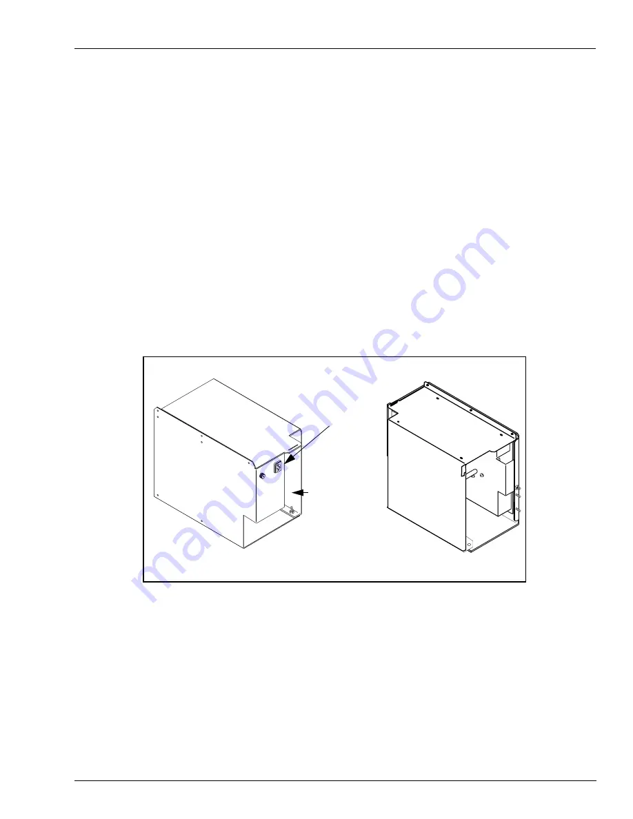
Prepare T20606-G3 card cage for installation.
Note: For more cable connection detail see “Addressing Gateway Board” on
1
Locate tab at left front top of card cage.
2
From B side of unit, turning card cage sideways to unit, feed top and rear of card
cage up and into shelf.
Note: Front of card cage will face B side.
3
Position card cage so that tab fits over latch cutout for main door latch to secure
card cage to shelf divider. Note position of two screws protruding from bottom of
card cage:
• For newer units, both screws will pass through holes in printer shelf.
• For older units, holes will not align with holes in shelf. Remove both screws
and save.
4
Position rear of card cage on edge of cabinet shelf for easy cable connection.
Note: Do not secure card cage at this time. Connecting cables and setting jump
jacks are easier if card cage can be manipulated by installer.
5
Connect three prong female end of power cable R20580-G2 to card cage at location
shown.
6
Locate harness attached to card cage containing P1 and P2 connectors.
Note: Cables are already connected to Gateway PCB T20678-G1 at J282A/P282A
and J282B/P282B.
7
Feed both harness cables down through hole as shown in illustration in Step 3 of
“Installing Cables” on page 20.
Rear
Connect
R20580-G2
3-prong end
Front
Locate harness
cables (with P1
and P2
connectors) -
feed through
this end
T20606-G3 Card Cage shown: Gateway Board located inside card cage


