background image

31

ENGLISH

BASIC 

CONNECTIONS

BASIC OPERA

TION

ADV

ANCED 

CONNECTIONS

SETUP

ADV

ANCED 

OPERA

TION

TROUBLESHOOTING

OTHERS

NAMES AND 

FUNCTIONS

ADV

ANCED 

OPERA

TION

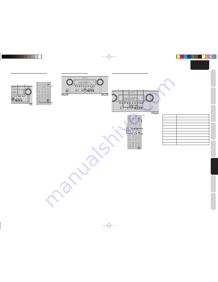
CLEARING STORED PRESET STATIONS

You can remove preset stations from the memory 
using the following procedure.

2.

3.

ST

V – OFF

NIGHT

PEAK

ANALOG

DIGITAL

ATT

DISC 6.1

MT X 6.1

SPKR

B

EQ

DIGITAL

SURROUND

AAC

PCM

L

C

R

SL

S

SR

LFE

2.

3.

 1.

  Recall the preset number to be cleared with 

the method described in “Recalling” a preset 
station.

 2.

 Press 

the 

MEMORY

 button on the front panel 

or press the 

MEMO

 button on the remote 

controller.

 3.

  The stored preset number blinks in the display 

for 5 seconds. While blinking, press the 

CLEAR 

button on the front panel or the 

CL

 button on the 

remote controller.

 4.

  “

xx CLEAR

” appears on the display to indicate 

that the specified preset number has been 
cleared.

Note: 

To clear all stored preset stations, press and hold the 

T.MODE

 and the 

ENTER

 buttons for two seconds.

NAME INPUT OF THE PRESET STATION.

This function allows the name of each preset channel 
to be entered using alphanumeric characters. 
Before name inputting, you need to store preset 
stations with the preset memory operation.

4.

5.

2.
5.
6.

DISP

MULTI

AUTO

TUNED

ST

V – OFF

NIGHT

PEAK

ANALOG

DIGITAL

ATT

SLEEP

SURR

AUTO

DIRECT

DISC 6.1

MT X 6.1

SPKR

B

EQ

DIGITAL

SURROUND

AAC

PCM

L

C

R

SL

S

SR

LFE

2. 5. 6.

5.

4.

5.

 1.

  Recall the preset number to be inputted name 

with the method described in “Recalling” a 
preset station.

 2.

 Press 

the 

MEMORY

 button on the front panel 

or press the 

MEMO

 button on the remote 

controller for more than 3 seconds.

 3.

  The left most column of the station name 

indicator fl ashes, indicating the character entry 
ready status.

 4.

  When you press the 

3

 or 

4

 cursor buttons on 

the front panel or the 

TUNE 

3

 / 

4

 buttons on 

the remote controller, alphabetic and numeric 
characters will be displayed in the following 
order:


 B 

 C ... Z 

 1 

 2 

 3 ..... 0 

 – 

 + 

 / 

 (Blank) 

 A


UP


DOWN

SORTING PRESET STATIONS

DISP

MULTI

AUTO

TUNED

ST

V – OFF

NIGHT

PEAK

ANALOG

DIGITAL

ATT

SLEEP

SURR

AUTO

DIRECT

DISC 6.1

MT X 6.1

SPKR

B

EQ

DIGITAL

SURROUND

AAC

PCM

L

C

R

SL

S

SR

LFE

If you have stations memorized, and there is a gap in 
the sequential order:
I.e. the stations are stored as follows 

 1) 

87.5 

MHz

 2) 

93.1 

MHz


 3)  94.7 MHz

 10) 

105.9 

MHz

(notice there is no stations programmed for pre sets 
for 4-9), you can have pre set 10 become pre set 4: 
To sort the numbers, press the 

4

 cursor button while 

pressing the 

MEMORY

 button.

PRESET SORT

” will appear on the display and 

sorting will be done.

 5.

  After selecting the fi rst character to be entered, 

press the 

MEMORY

 or 

ENTER

 buttons, press 

the 

MEMO

 button on the remote controller. 

     The entry in this column is fi xed and the next 

column starts to fl ash. Fill the next column the 
same way.


  To move back and forth between the characters, 

press the 

1

 / 

2

 cursor buttons or press 

PRESET


or 

 buttons on the remote controller.

Note: 

Unused columns should be fi lled by entering blanks.

 6.

  To save the name, press the 

MEMORY

 button 

on the front panel or remote controller for more 
than 2 seconds.

Ten keypad

Press, press again, press again, etc.

1

 B 

 C 

 1 

 A

2

 E 

 F 

 2 

 D

3

 H 

 I 

 3 

 G

4

 K 

 L 

 4 

 J

5

 N 

 O 

 5 

 M

6

 Q 

 R 

 6 

 P

7

 T 

 U 

 7 

 S

8

 W 

 X 

 8 

 V

9

 Z 

 space 

 9 

 Y

0

– 

 + 

 / 

 0

SR4003̲U̲01̲E2̲2.indd   31

SR4003̲U̲01̲E2̲2.indd   31

08.6.20   5:06:30 PM

08.6.20   5:06:30 PM

Summary of Contents for SR4003

Page 1: ...AV Surround Receiver SR4003 ENGLISH FRANÇAIS ESPAÑOL SR4003 U 00 cover indd 3 SR4003 U 00 cover indd 3 08 6 20 5 05 13 PM 08 6 20 5 05 13 PM ...

Page 2: ... designed to provide reasonable protection against harmful interference in a residential installation This equipment generates uses and can radiate radio frequency energy and if not installed and used in accordance with the instructions may cause harmful interference to radio communications However there is no guarantee that interference will not occur in a particular installation If this equipmen...

Page 3: ...ry cloth 7 Do not block any ventilation openings Install in accordance with the manufacture s instructions 8 Do not install near any heat sources such as radiators heat registers stoves or other apparatus including amplifiers that produce heat 9 Do not defeat the safety purpose of the polarized or grounding type plug A polarized plug has two blades with one wider than the other A grounding type pl...

Page 4: ... FEATURES 2 BEFORE USE 2 OPERATION OF REMOTE CONTROLLER 3 NAMES AND FUNCTIONS 4 FRONT PANEL 4 FL DISPLAYAND INDICATOR 5 REMOTE CONTROLLER 6 REAR PANEL 8 BASIC CONNECTIONS 9 SPEAKER PLACEMENT 9 CONNECTING SPEAKERS 10 CONNECTING AUDIO COMPONENTS 11 CONNECTING VIDEO COMPONENTS 12 CONNECTING HDMI COMPONENTS 13 CONNECTING THE ANTENNATERMINALS 14 CONNECTING THE AC POWER CABLE 14 BASIC OPERATION 15 AMP O...

Page 5: ...ibration available Improved Station Name Input Method 50 Presets Auto Adjust Function for Speaker Distance Settings Delay Time 7 80 Watts 8 Ohm Discrete Amplifiers Massive Energy Power Supply Huge EI Transformer 192 kHz 24 bit Crystal DAC for all 8 Channels 32 bit Digital Surround Processing Chipsets Large Heavy Duty Speaker Terminals for all Channels Auto Input Signal Detection Front AUX Input Di...

Page 6: ...the battery cover 2 Load the two new size AAA batteries inside the battery compartment while taking care to align their polarities correctly with the polarity markings with and with 3 Close the battery cover until it clicks shut CAUTIONS ON BATTERIES Use AAA type batteries in this remote controller We recommend that you use alkali batteries If the remote controller does not operate from close to t...

Page 7: ... PCM L C R SL S SR LFE q w 3 e t y 0 1 r u i o 2 4 5 6 7 8 9 u MENU button Press this button to enter the SETUP MAIN MENU i EXIT button Press this button to exit from the SETUP MAIN MENU o BAND button Press this button to switch between FM and AM in the TUNER mode 0 T MODE button Press this button to select the auto stereo mode or mono mode when the FM band is selected AUTO indicator will be illum...

Page 8: ...ller 0 EQ mode indicator This indicator is illuminated when the HT EQ function is active 1 ATT Attenuation indicator This indicator is illuminated when the attenuation function is active 2 DIGITAL Input Indicator This indicator is illuminated when a digital input has been selected 3 ANALOG input indicator This indicator is illuminated when an analog input source has been selected 4 SIGNAL FORMAT i...

Page 9: ...left right and subwoofer speaker When TV DSS mode are selected These buttons are used to change the channels 8 TREBLE CAT buttons When AMP mode is selected These buttons are used to adjust the tone control of high frequency sound for left and right speaker 9 CL Clear HT EQ button This button is used to erase the memory or program of a source include the Tuner mode When AMP mode is selected This bu...

Page 10: ... When AMP mode is selected 1 AUTO button This button is used to select auto surround 2 STEREO button This button is used to select STEREO mode 3 P DIRECT button When this button is pressed once SOURCE DIRECT mode is selected If pressed again PURE DIRECT mode is selected 4 SLEEP button This button is used for setting the sleep timer 5 M DAX button This button is not used for this unit 6 EQ button T...

Page 11: ...rt you can playback the audio with 5 1 channel or 7 1 channel outputs e VIDEO IN OUT TV DVD VCR DSS These are the video inputs and outputs There are 4 video inputs and 2 video outputs and each one includes both composite video and S video configurations Connect VCRs DVD players and other video components to the video inputs The 2 video output channels can be used to be connected to video tape reco...

Page 12: ...ight Front Left Front Center Surround Left Subwoofer Surround Back Left Surround Right Front left and right speakers We recommend to set the front L and R speakers with 45 60 degrees from the listening position Center speaker Align the front line of the center speaker with the front L R speakers Or place the center speaker a little backward from the line Surround left and right speakers When this ...

Page 13: ...R4003 MODEL NO SR4003 INPUT 3 INPUT 3 OUTPUT OUTPUT INPUT 2 INPUT 2 INPUT 1 INPUT 1 IN IN FLASHER FLASHER SW SW PRE OUT PRE OUT R R SPEAKER SYSTEMS 6 8 OHMS SPEAKER SYSTEMS 6 8 OHMS R R L L L L L L R R CENTER CENTER FRONT FRONT SURROUND BACK SURROUND BACK S SPEAKER B S SPEAKER B SURROUND SURROUND Powered subwoofer Surround BACK Center Left Surround Right Front A Right Left Right Left CONNECTING SP...

Page 14: ...al RF demodulator Dolby Digital decoder when connecting the Dolby Digital RF output jack of the video disc player to the digital input jack The digital signal jacks on this unit conform to the EIA standard If you use a cable that does not conform to this standard this unit may not function properly Each type of audio jack works independently Signals input through the digital and analog jacks are o...

Page 15: ...N IN OUT OUT C CR R P PR R C CB B P PB B Y Y DSS DSS TV TV DVD DVD VCR IN VCR IN VCR OUT VCR OUT MONITOR OUT MONITOR OUT INPUT INPUT 1 1 INPUT INPUT 2 2 S VIDEO S VIDEO VIDEO VIDEO PRE OUT PRE OUT CENTER CENTER FRONT FRONT SURROUND BACK SURROUND BACK S SPEAKER B S SPEAKER B SURROUND SURROUND MONITOR MONITOR OUT OUT INPUT INPUT 3 3 C COMPONENT VIDEO 2 2 1 1 4 4 3 3 7 1CH INPUT 7 1CH INPUT AUX 2 AUX...

Page 16: ...is unit turn power to unused components off to prevent interference between them Disconnecting or connecting cables with the power on can damage the equipment Turn the power off before disconnecting or connecting cables Some DVD Audio disks disable downmixing These types of disks are not played back correctly unless the left center right and surround left and right speakers and subwoofer are conne...

Page 17: ...TEMS 6 8 OHMS R R L L L L L L R R IN IN OPT OPT DIGITAL OUT DIGITAL OUT L L SL SL C C SBL SBL R R SR SR SW SW SBR SBR R R L L FM FM 75 75Ω Ω GND GND AM AM C CR R P PR R C CB B P PB B Y Y ANTENNA ANTENNA DIGITAL IN DIGITAL IN OUT OUT IN IN CD CDR CD CDR OUT OUT IN IN TAPE TAPE VCR VCR DVD DVD TV TV AUDIO AUDIO DSS DSS IN IN OUT OUT C CR R P PR R C CB B P PB B Y Y DSS DSS TV TV DVD DVD VCR IN VCR IN...

Page 18: ...omponent video input is connected to the DVD or DSS component inputs it will be routed to the Component Video Output Make certain that your TV is set to the proper input to view the signal ADJUSTING THE MAIN VOLUME ANALOG DIGITAL DIGITAL SURROUND AAC PCM L C R SL S SR LFE Adjust the volume to a comfortable level using the VOLUME control knob on the front panel or VOLUME 3 4 buttons on the remote c...

Page 19: ...nit 1 To select tuner and desired band FM or AM press the BAND button on the front panel 2 Press the 3 or 4 cursor buttons on the front panel to select the desired station Using the remote controller 1 To select tuner and desired band FM or AM press the BAND button on the remote controller 2 Press the TUNE 3 or 4 on the remote controller to tune in the desired station DIRECT FREQUENCY CALL 1 3 2 1...

Page 20: ...EREO 2 Selects STEREO mode P DIRECT 3 Selects the pure direct mode SLEEP 4 Sets the sleep timer function NIGHT 8 Turns on or off NIGHT mode V OFF 9 Turns on or off video output HT EQ CL Turns on or off HT EQ mode CH SEL 0 Calls up CH LEVEL ADJUST and adjusts speaker levels or 7 1ch input level TV POWER Turns the TV on and off TV INPUT Selects the TV video input TREBLE Adjusts the tone control of h...

Page 21: ...R L R FRONT SURR SURR BACK SUB WOOFER CENTER R L R L R L L R DVD Audio player or Super Audio CD Multi channel player ADVANCED CONNECTIONS CONNECTING AN EXTERNAL POWER AMPLIFIER The PREOUT jacks are for connecting external power amplifiers Be sure to connect each speaker to the corresponding external power amplifier R R SR SR C C SW SW SBR SBR SL SL SBL SBL L L L L SL SL C C SBL SBL R R SR SR SW SW...

Page 22: ... INPUT 2 2 CENTER CENTER FRONT FRONT SURROUND BACK SURROUND BACK S SPEAKER B S SPEAKER B SURROUND SURROUND AC IN AC IN MONITOR MONITOR OUT OUT INPUT INPUT 3 3 COMPONENT COMPONENT VIDEO VIDEO OUT OUT REMOTE CONT REMOTE CONT 2 2 1 1 4 4 3 3 AC OUTLETS AC OUTLETS 120V 60Hz 120V 60Hz SWITCHED SWITCHED 1 25A 150W 1 25A 150W MODEL N MODEL NO SR4003 INPUT 1 INPUT 1 IN IN FLASHER FLASHER IN IN OUT OUT REM...

Page 23: ...MAIN RETURN EXIT 3 PREFERENCE STANDBY MODE ECONOMY TV AUTO DISABLE OSD INFO ENABLE VIDEO CONVERT HDMI ENABLE MAIN EXIT 1 2 INPUT SETUP FUNC MODE DIG HDMI COMP TAPE AUTO CD R AUTO 4 AUX2 AUTO MAIN RETURN EXIT 2 1 SPEAKER SETUP SPEAKER SETUP AUTO SET MICROPHONE MAIN NEXT EXIT 2 3 SPEAKERS DISTANCE DISTANCE UNIT m FRONT L 3 0 m FRONT R 3 0 m CENTER 3 0 m SURR L 3 0 m SURR R 3 0 m SUB W 3 0 m SURR B L...

Page 24: ... following characteristics 1 Select SPEAKER SETUP in SETUP MAIN MENU with 3 or 4 cursor button and press the ENTER button 2 1 SPEAKER SETUP Speakers are set up by selecting either MANUAL or AUTO using the 1 and 2 cursor buttons For operation when AUTO has been selected see MRAC on page 23 2 1 SPEAKER SETUP SPEAKER SETUP MANUAL MAIN NEXT EXIT 2 2 SPEAKERS SIZE When setting the speaker size in the S...

Page 25: ...e from the surround left speaker to your normal listening position SURR R Set the distance from the surround right speaker to your normal listening position SUB W Set the distance from the subwoofer to your normal listening position SURR B L Set the distance from the surround back left speaker to your normal listening position SURR B R Set the distance from the surround back right speaker to your ...

Page 26: ... MRAC feature is available except in the following modes 7 1 CH INPUT PURE DIRECT SOURCE DIRECT 3 Select 2 SPEAKER SETUP on the SETUP MAIN MENU then select AUTO for 2 1 SPEAKER SETUP Move the cursor to NEXT with the 3 or 4 cursor buttons and then press the ENTER button 2 1 SPEAKER SETUP SPEAKER SETUP AUTO SET MICROPHONE MAIN NEXT EXIT 4 Select START on the AUTO SETUP display and press the ENTER bu...

Page 27: ... and harsh when played back over audio equipment in the home This is because film soundtracks were designed to be played back in large movie theater environments Activating the HT EQ feature when watching a film made for movie theaters corrects this and restores the correct tonal balance The HT EQ feature is available except in the following modes 7 1 CH INPUT PURE DIRECT SOURCE DIRECT When VIRTUA...

Page 28: ...ner at the same level 7 7 1 CH INPUT LEVEL VIDEO IN LAST FRONT L 0 dB CENTER 0 dB FRONT R 0 dB SURR R 0 dB SURR B R 0 dB SURR B L 0 dB SURR L 0 dB SUB W 0 dB MAIN EXIT 1 Select 7 1CH INPUT in the SETUP MAIN MENU with the 3 or 4 cursor buttons and press the ENTER button 2 To select VIDEO IN press 3 or 4 cursor button 3 Using the 1 or 2 cursor buttons select the video input source which is emitted f...

Page 29: ...ion the audio or video source selected for listening through this unit is sent to the record outputs This means that any program you are watching or listening to may be recorded simply by placing machines connected to the outputs for TAPE OUT CD CDR OUT VCR OUT in the record mode To record the input source signal you are currently watching or listening to 1 DISP MULTI AUTO TUNED SLEEP SURR AUTO DI...

Page 30: ... turn off the Night mode press the NIGHT button again LISTENING THROUGH HEADPHONES This jack may be used to listen to the unit s output through a pair of headphones Be certain that the headphones have a standard 1 4 stereo phono plug Note that the speakers will automatically be turned off when the headphone jack is in use DISP MULTI AUTO TUNED ST V OFF NIGHT PEAK ANALOG DIGITAL ATT SLEEP SURR AUTO...

Page 31: ... controller To cancel the 7 1 CH INPUT setting press 7 1 on the remote controller Notes 7 1 CH Input mode bypasses the internal surround processing so SURROUND mode cannot be selected In addition there is no signal at the record outputs when the 7 1 CH Input is in use AUX2 INPUT If you don t need to connect 7 1 Ch input terminals with multi channel decoder L front left and R front right inputs ter...

Page 32: ... be converted from the video to component or S Video DISP MULTI AUTO TUNED ST V OFF NIGHT PEAK ANALOG DIGITAL ATT SLEEP SURR AUTO DIRECT DISC 6 1 MTX 6 1 SPKR B EQ DIGITAL SURROUND AAC PCM L C R SL S SR LFE VIDEO S VIDEO COMPONENT The signal cannot be converted from the component to the video or S video Notes of OSD menu The setup menu can be displayed through all video out COMPONENT S VIDEO VIDEO...

Page 33: ...hen all 50 preset memory positions are filled or when auto scanning attains the highest end of all bands If you desire to stop the auto preset memory at anytime press the CLEAR button Note It is possible that existing preset memory positions will be overwritten MANUAL PRESET MEMORY 2 3 DISP MULTI AUTO TUNED ST V OFF NIGHT PEAK ANALOG DIGITAL ATT SLEEP SURR AUTO DIRECT DISC 6 1 MTX 6 1 SPKR B EQ DI...

Page 34: ...e controller for more than 3 seconds 3 The left most column of the station name indicator flashes indicating the character entry ready status 4 When you press the 3 or 4 cursor buttons on the front panel or the TUNE 3 4 buttons on the remote controller alphabetic and numeric characters will be displayed in the following order A B C Z 1 2 3 0 Blank A UP DOWN SORTING PRESET STATIONS DISP MULTI AUTO ...

Page 35: ...p menu of the DVD player DISPLAY AMP function enabled MUTE AMP function enabled SURR AMP function enabled VOLUME AMP function enabled TOP Calls up the top menu of DVD disc INFO Displays the disc information Cursor Moves the cursor for setting in On Screen Display mode ENTER Enters the setting MENU Calls up the menu of DVD disc EXIT Exits from SETUP MENU T TONE AMP function enabled PAUSE PAUSE PLAY...

Page 36: ...ed MUTE AMP function enabled SURR AMP function enabled VOLUME AMP function enabled TOP AMP function enabled INFO AMP function enabled Cursor AMP function enabled ENTER AMP function enabled MENU AMP function enabled EXIT AMP function enabled T TONE AMP function enabled PAUSE PAUSE PLAY PLAY STOP STOP Previous Next Sk ips forward or prev ious chapter track Rewind Forward Searchs forward or backward ...

Page 37: ... by numeric buttons for appliance code table at the end of this book When the procedure is successful the SEND indicator will blink twice Note If the indicator did not blink twice then repeat steps 1 through 2 and try entering the same code again SCANNING THE CODE TABLE 3 5 2 3 2 1 Switch on the appliance which should be controlled BASIC OPERATION REMOTE CONTROLLER NORMAL MODE When operating Maran...

Page 38: ...d programming the remote controller press the SET button then LEARN indicator stops blinking and exits from the LEARN mode Notes When the SEND indicator blinks once again the transmitting code is unavailable for remote controller or the transmitting signal is intercepted by noise If no buttons are pressed for approximately 1 minutes while in the LEARN mode the remote controller automatically exits...

Page 39: ...ONE has been selected in SETUP mode Make the correct setting No Audio output from the surround back speakers The surround back speaker cable connection is incomplete Connect the cable correctly Surround mode is not EX ES mode Set surround mode EX ES Surroundback NONEhasbeenselected in SPEAKERS SIZE SETUP Make the correct setting SYMPTOM CAUSE REMEDY Can not select EX ES mode Surround center NONE h...

Page 40: ...OG DIGITAL ATT SLEEP SURR AUTO DIRECT DISC 6 1 MTX 6 1 SPKR B EQ DIGITAL SURROUND AAC PCM L C R SL S SR LFE SURROUND MODE PURE DIRECT EXIT CLEAR FRONT KEY BUTTON LOCK OF THE UNIT If the PURE DIRECT and EXT buttons on the front panel are both pressed at the same time for three seconds or more all the buttons on the front panel excluding the POWER ON OFF button as well as the INPUT SELECTOR knob and...

Page 41: ...o 6 Music DTS ES DTS 5 1 O O O O dts ES L C R SL SR S LFE DTS 96 24 DTS 96 24 O O O O dts 96 24 L C R SL SR LFE DTS 5 1ch DTS 5 1 O O O O dts L C R SL SR LFE PCM Audio Neo 6 O O O O O PCM L R Analog Neo 6 O O O O O ANALOG Dolby D 2ch Neo 6 O O O O O 2 DIGITAL L R Dolby D 2ch Surr Neo 6 O O O O O 2 DIGITAL 2 SURROUND L R S CS II Cinema CS II Music CS II Mono PCM Audio CS II O O O O O PCM L R Analog...

Page 42: ...am sources from DVD etc DTS ES Discrete 6 1 features digital discrete recording of all channels including the surround back channel s and higher quality of audio reproduction DTS ES is not available in the system without a surround back speaker Dolby MODE Dolby Digital Pro Logic IIx MOVIE Pro Logic IIx MUSIC Pro Logic IIx GAME Pro Logic This mode is used with source materials encoded in Dolby Digi...

Page 43: ...for VCR 1 OUT DSS VCR 2 OUT TAPE OUT and CD R OUT output analog audio signals only Do not record from CDs or LDs that support DTS using these outputs If you do the DTS encoded signal will be recorded as noise NOTE for Dolby Digital Surround EX signal When playing Dolby Digital Surround EX encoded software in 6 1 channels it is required to set the EX ES mode Note that some of Dolby Digital Surround...

Page 44: ...X should be used with movies soundtracks recorded with Dolby Digital Surround EX About Dolby Pro Logic IIx Dolby Pro Logic IIx technology delivers a natural and immersing 7 1 channel listening experience to the home theater environment A product of Dolby s expertise in surround sound and matrix decoding technologies Dolby Pro Logic IIx is a complete surround sound solution that maximizes the enter...

Page 45: ...dB GENERAL Power Requirement AC 120 V 60Hz Power Consumption 500 W Weight 25 6 lbs 11 6 kg ACCESSORIES Remote Controller 1 AAA size batteries 2 FM Antenna 1 AM Loop Antenna 1 AC Power Cord 1 Microphone MC 10 1 User Guide 1 Specifications subject to change without prior notice CLEANING OF EQUIPMENT EXTERNAL SURFACES The exterior finish of your unit will last indefinitely with proper care and cleani...

Page 46: ...53 Radio Shack 1003 1013 1015 1023 1024 1025 1045 1100 1103 1110 1113 RCA 1003 1004 1005 1006 1007 1008 1014 1024 1049 1069 1075 1079 1085 1087 1088 1093 1094 1101 1103 1110 1113 1153 Realistic 1013 1015 1023 1025 1045 1100 1103 1110 Runco 1010 1153 Sampo 1150 Samsung 1003 1013 1024 1026 1040 1045 1062 1078 1083 1090 1100 11051114 1120 1121 1146 1148 1157 Sansui 1119 Sanyo 1003 1025 1051 1072 1077...

Page 47: ...2041 Samsung 2008 2012 2022 2024 2027 Sanyo 2050 2052 Sharp 2044 2045 Sherwood 2051 Sony 2001 2013 2059 Toshiba 2004 2008 2026 2028 Yamaha 2046 2060 Zenith 2010 DSS Alphastar 4027 Amstrad 4046 4047 4050 Atsky 4048 B Sky B 4021 4045 4046 Chaparral 4039 DIRECTV 4001 4016 4044 DISH Network 4030 Drake 4026 Echostar 4007 4017 4018 4019 4020 4062 4063 4064 Eurosky 4047 4056 Express Vu 4017 Foxtel 4051 F...

Page 48: ... find your nearest authorized distributor or dealer on our website is a registered trademark 06 2008 541110122025M mzh d Printed in China SR4003 U 00 cover indd 2 SR4003 U 00 cover indd 2 08 6 20 5 05 13 PM 08 6 20 5 05 13 PM ...

Reviews: