32
END
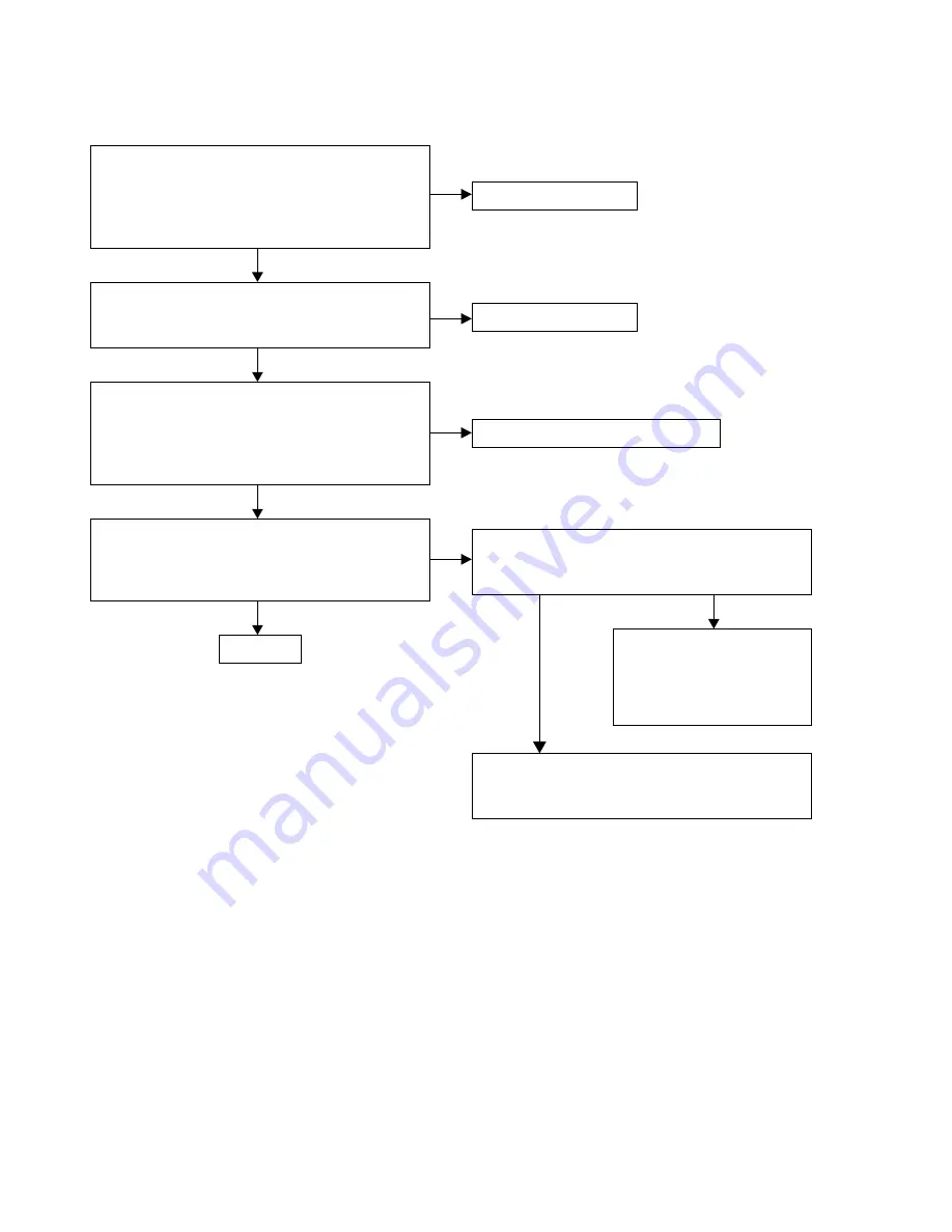
3. No Sound, Noise generated
3.1. COMMON
Is the wire properly inserted ?
• AUDIO PCB
• CN98
Check DC voltage
• AUDIO PCB
• IC71 pin3: +5V
• Q653 emitter : +15V
• Q654 emitter: -15V
Has the mute drive been cut in the playback mode?
• AUDIO PCB
• D763 Cathode : -14V
Is the Fuse opened?
• AUDIO PCB
• F601
• F602
• F603
Replace each Fuse.
Insert the wire properly.
Check Soldering or replace each device.
Check the control signal in playback mode?
•
AUDIO PCB
• WF61 19
pin : playback mode : +3.3V
Check Soldering or replace
• DIGITAL PCB
• IC11
or
• AUDIO PCB
• IC70
YES
NO
NO
NO
YES
YES
YES
YES
NO
NO
Check soldering or replace.
• Q631, D763, D764
Summary of Contents for NA8005
Page 8: ...Personal notes 8 ...
Page 24: ...19 Personal notes ...
Page 38: ...38 Personal notes ...
Page 43: ...WIRING DIAGRAM 43 ...
Page 56: ...Personal notes Personal notes 56 ...
Page 62: ...62 PCM9211 DIGITAL IC42 PCM9211 Block Diagram ...
Page 63: ...63 PCM9211 Pin Discriptions ...
Page 66: ...66 CS2000 CP DIGITAL IC43 CS2000 CP Block Diagram ...
Page 69: ...69 MFI337S3959 DIGITAL IC25 ...
Page 70: ...70 2 DISPLAY S020 MXS4035A 3 ...


