MANDÍK CPV Installation, commissioning, and maintenance
IZU 02/2021
MANDÍK, a.s., www.mandik.cz
R
28
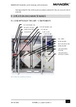
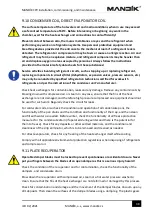
Fig 12 Airflow, right-hand unit design
9.2
DESCRPTION OF THE UNIT
–
CONTROL SYSTEM
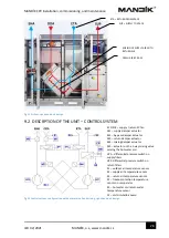
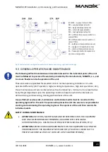
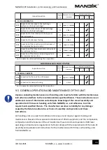
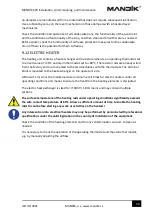
Fig 13 Control system, configuration with hot water coil and mixing, right-hand unit design
SUP = SUPPLY TO SPACE
ETA = RETURN FROM SPACE
MIXING OF SUPPLY AIR WITH
RETURN AIR
FRESH AIR BY-PASS
EC1/EC2
–
supply / return EC fan
M1
–
supply damper actuator
M2
–
by-pass damper actuator
M3
–
return damper actuator
M4
–
mixing damper actuator
M5
–
actuator on the 3-way mixing valve
serving the hot water coil
dP1
–
differential pressure switch on
supply filters
dP2- differential pressure switch on
return filters
S1
–
outdoor air temperature sensor
S2
–
supply air temperature sensor
S3
–
return air temperature sensor
S4
–
freeze-protection temperature
sensor on recuperator
S5
–
hot water coil return water
temperature sensor
CP
–
coil circulating pump

