background image

MANDÍK CPV Installation, commissioning, and maintenance


IZU  02/2021 

MANDÍK, a.s., www.mandik.cz


R

19 

7


ACTIVITIES PRIOR TO COMMISSIONING 

7.1


GENERAL 


The unit may only be commissioned by instructed and trained personnel and with full 
adherence to applicable safety regulations and standards. 


Prior to commissioning, it is necessary to complete all the previous steps in the 
installation instructions. 


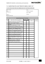
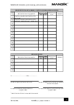
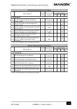
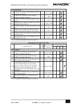
Prior to commissioning, the individual steps below must be completed and recorded 
in a suitable protocol that is then attached to the operating documentation and a copy 

of which must be sent by post to MANDÍK, a.s. or via email to our service centre at 

[email protected]

. 


The following paragraph with instructions may be followed step-by-step when 
inspecting the individual parts of the unit and which is created as a protocol and may 
be used as a suitable guide for the commissioning process. 


Summary of Contents for 0789-0010

Page 1: ...MANDÍK CPV Installation commissioning and maintenance IZU 02 2021 MANDÍK a s www mandik cz R 1 CPV Compact Air Handling Units INSTALLATION COMMISSIONING MAINTENANCE R ...

Page 2: ...IZU 02 2021 MANDÍK a s www mandik cz R 2 Contact MANDÍK a s Dobříšská 550 267 24 Hostomice Czech Republic tel 420 311 706 706 fax 420 311 584 810 email mandik mandik cz service department email service mandik cz Copyright MANDÍK a s 2021 Subject to change ...

Page 3: ... HVAC DUCTWORK 14 6 6 CONDENSATE DRAIN TRAP CONNECTION 14 6 7 HOT COLD WATER COIL CONNECTIONS 15 6 8 ELECTRICAL CONNECTIONS 17 7 ACTIVITIES PRIOR TO COMMISSIONING 19 7 1 GENERAL 19 7 2 INSPECTING THE UNIT PRIOR TO INITIAL START UP 20 7 3 CONFIGURATION OF THE CONTROL SYSTEM FOR UNIT START UP 22 8 COMMISSIONING 22 8 1 ACTIVITIES PRIOR TO INITIAL START UP 22 8 2 ACTIVITIES DURING INITIAL START UP 23 ...

Page 4: ...ATER COIL COLD WATER COIL 37 9 10 CONDENSER COIL DIRECT EVAPORATOR COIL 38 9 11 PLATE RECUPERATOR 38 9 12 ELECTRIC HEATER 39 ANNEX A QUICK FAN ADJUSTMENT POL871 HMI CONTROLLER 43 ANNEX B QUICK STARTING THE UNIT WEB POL871 HMI CONTROLLER 45 ANNEX C QUICK STARTING THE UNIT POL822 ROOM UNIT 46 ANNEX D MAINS CONNECTION HOT WATER HEATING 49 ANNEX E MAINS CONNECTION ELECTRIC HEATING 50 ANNEX F PERIPHERA...

Page 5: ...proper operation and functionality and to comply with warranty conditions The manufacturer is not liable and the user bears all risks for any damage resulting from improper use This manual is intended for personnel with valid authorisation and licenses to conduct service work on ventilation and air handling units CPV air handling units are designed for central distribution and conditioning of air ...

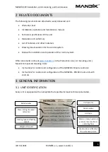
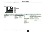
Page 6: ...ments online at www mandik cz in the Production Line Air Handling units Mandík Compact Air Handling Units Instructions for control and configuration of the SIEMENS Climatix controller Instructions for control and configuration of the SIEMENS POL822 room unit with controls 3 GENERAL INFORMATION 3 1 UNIT IDENTIFICATION Every unit is equipped with a nameplate that specifies its basic technical parame...

Page 7: ...utlets 3rd character outlets 3 electric heater 2nd character medium 6 M6 0 supply damper not installed 0 all outlets up V vertical 2nd character medium 1 water 7 F7 1 internal supply damper 1 SUP EHA upper wall H horizontal 0 none electric heater 2 R410A refrigerant 8 F8 2 external supply damper 2 SUP EHA side walls 1 water 3 R407C refrigerant 9 F9 3rd character return damper 3 SUP upper wall EHA ...

Page 8: ...ds safety regulations and generally accepted technical rules must be followed during assembly wiring commissioning repairs and maintenance of the unit Only natural persons or legal entities with valid authorisation are permitted to conduct assembly of the unit including electrical wiring commissioning repairs maintenance and operation The following general instructions are considered absolutely ne...

Page 9: ... individually ATTENTION the plastic film is protected by shipping packaging to protect the chamber during transport and must not be used for long term storage of the chamber Changes in temperature during transport may result in water vapour condensing inside the packaging and create suitable conditions to result in corrosion of the materials used in the chambers e g white corrosion on galvanised c...

Page 10: ... pallet truck Openings are provided in the frame of the units for handling During use pallet truck forks must remain fully under the chamber 2 Preparation and handling using a forklift Openings are provided in the frame of the chamber for handling During use the forklift forks must remain fully under the chamber see the illustration ATTENTION The chamber is not evenly balanced in terms of weight H...

Page 11: ...e unit in its horizontal working position To prevent deformation in the unit at the locations where pressure is applied by straps ensure the straps are properly spaced above the unit or these points are protected with sufficiently rigid reinforcement ATTENTION Only suitable and permitted rigging equipment may be used for handling and transport of units Comply with all valid technical regulations a...

Page 12: ...e maintained to the wiring panel to which the systems are connected Power components circuit breakers contactors switches etc must be clearly labelled in the wiring panel with the number of the equipment per the HVAC project We recommend a representative of the assembling organisation and the user attend operator training The unit cannot perform any structural functions such as supporting the stat...

Page 13: ... under the frame of the unit at the place of installation The maximum permitted deviation from the horizontal is 0 5 0 3 The unit must be installed at a sufficient height above the floor ground to provide sufficient trap height on chambers equipped with condensate drains see the Subsection 6 6 TRAP ASSEMBLY Failure to ensure sufficient stability or levelness of the surface may degrade the function...

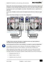
Page 14: ...lements must be properly sealed Specification of the supply return connections on the unit Fig 1 outlets right hand design of CPV unit Fig 2 outlets left hand design of CPV unit 6 6 CONDENSATE DRAIN TRAP CONNECTION The condensate drain must be connected through a trap with a sufficient water column height to ensure flawless operation A trap connection under vacuum must always be filled with water ...

Page 15: ... pressure values is as follows Fig 3 Vacuum trap with ball HL136NGG May be used at vacuum up to 2300 Pa H P 10 P value of the pressure specified in the technical specifications of the unit Pa Fig 4 Trap connection point 6 7 HOT COLD WATER COIL CONNECTIONS All piping must be anchored separately from the heat exchangers Piping systems conveying the working media may not exert pressure due to their w...

Page 16: ...guration A capillary freeze protection thermostat is integrated into the unit fully installed and connected to the control system from the factory The mixing loop for heat control if part of delivery is provided in a separate cardboard box The installation and service manual is attached to the mixing loop packaging The manual provides detailed information on safe installation commissioning and mai...

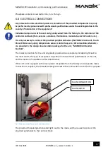
Page 17: ...POL822 room unit Touch Panel CO2 sensor piping temperature sensor control loop etc All connection schematics are provided in the design documentation package for the unit MANDÍK Air Handler Controls The mains connection for the unit is typically provided via a receptacle installed right next to the main switch The type of receptacle is specified in the technical specifications of the unit and the ...

Page 18: ... connection schematic for models with a hot water coil is provided in Annex D The mains connection schematic for models with an electric heater is provided in Annex E The connection schematic for peripherals the CO2 sensor POL822 room unit and exterior outdoor air temperature sensor is provided in Annex F ...

Page 19: ... the previous steps in the installation instructions Prior to commissioning the individual steps below must be completed and recorded in a suitable protocol that is then attached to the operating documentation and a copy of which must be sent by post to MANDÍK a s or via email to our service centre at service mandik cz The following paragraph with instructions may be followed step by step when ins...

Page 20: ...eanness of the chamber interior without foreign bodies and construction Check closing of the unit the door service panels Check the mounting of the roof on outdoor units acc to installation instructions Check the tightness of chamber connections visually acc to installation instructions OPERATIONS FOR THE UNIT IN GENERAL Check the seating order of the chambers within the unit acc to the documentat...

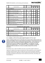
Page 21: ...erator s authorised representative in capital letters in capital letters Record the value only w hen a value needs to be measured SPECIAL OPERATIONS Completion of operation Measured or set value Check the connection and condition of the peripherals external sensors remote control OPERATIONS FOR THE UNIT IN GENERAL ELECTRICAL AND MEASURING AND CONTROL Opera tion numb Description of servicing operat...

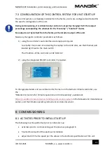
Page 22: ...process of connecting the laptop to the controller use the Ethernet port located right next to the main switch The IP address of the controller is 192 168 1 42 2 using the integrated POL871 controller if provided To change parameters and as a reference for the menu in the Siemens Climatix controller use the Detailed instructions for Climatix operation and commissioning available at https mandik cz...

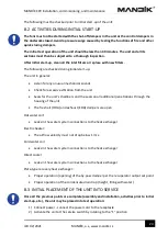
Page 23: ... from the unit Seals for the unit s chambers and the seals on all additional penetrations through the housing of the unit The fresh air ODA and exhaust EHA dampers are open Hot water coil Leaks in the water system connections to the heat exchanger Electric heater The airflow velocity must not drop below 1 m s Cold water coil Leaks in the water system connections to the heat exchanger Direct cooler...

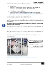
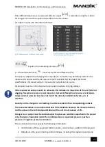
Page 24: ...g the activities in the previous paragraph 8 3 the air output of the unit must be checked per requirements or the speed must be adjusted using the EC fan controller Quick supply return fan output settings are provided in Annex A QUICK FAN ADJUSTMENT WEB POL871 HMI CONTROLLER Placing the unit into service operating mode is specified in Annex B QUICK STARTING THE UNIT POL871 HMI CONTROLLER or Placin...

Page 25: ...dicates an inspection of the unit internal clogging foreign local pressure resistances or ductwork foreign local pressure resistances design external pressure loss does not match the actually installed ductwork etc is required An entry on the changes to unit settings must be recorded in the corresponding protocol The measured values are considered suitable if the deviation between the measured val...

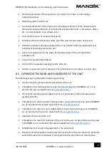
Page 26: ...ts etc 8 5 OPERATOR TRAINING AND HANDOVER OF THE UNIT The following steps must be performed during training User training for operation and maintenance of the unit Completion of a training record A copy shall be sent by post to MANDÍK a s or via email to the service department at service mandik cz Training for operating and configuration of user parameters of the Climatix control system controller...

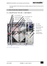
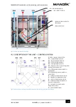
Page 27: ...nit control protocol 9 OPEATION AND MAINTENANCE 9 1 DESCRIPTION OF THE UNIT COMPONENTS Fig 11 Components right hand unit design ACCESS TO THE PANEL MAIN SWITCH FILTER RETURN MIXING DAMPER HEAT RECOVERY BY PASS FAN SUPPLY BY PASS DAMPER SHUT OFF DAMPER EHA FILTER SUPPLY MAINS CONNECTION SHUT OFF DAMPER ODA FAN RETURN HEAT EXCHANGER 1 HEATING COOLING HEAT EXCHANGER 2 HEATING ...

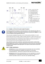
Page 28: ...RESH AIR BY PASS EC1 EC2 supply return EC fan M1 supply damper actuator M2 by pass damper actuator M3 return damper actuator M4 mixing damper actuator M5 actuator on the 3 way mixing valve serving the hot water coil dP1 differential pressure switch on supply filters dP2 differential pressure switch on return filters S1 outdoor air temperature sensor S2 supply air temperature sensor S3 return air t...

Page 29: ...ormed service work maintenance and technical audits must be recorded in the operating log book for the unit The person who places the unit into service is responsible for creating and maintaining the operating log book The operator of the unit then records the individual events SAFETY DURING MAINTENANCE ATTENTION ANY WORK MAINTENANCE AND INTERFERENCE INTO THE EQUIPMENT MAY ONLY BE PERFORMED BY PER...

Page 30: ... in the following paragraphs 9 5 and the individual parts of the unit 1 3 6 12 1 UNIT IN GENERAL 1 01 N cleaning and repair 1 02 Y repair 1 03 Y repair 1 04 Y repair 1 05 Y measuring 1 06 1 07 status of unit operation while performing the checks SERVICING AND MAINTENANCE OPERATIONS Unit in operation Y N Check operation Overall check of cleaning damage and corrosion on all components of the unit ou...

Page 31: ...he filter elements Check the setting and function of the differential pressure gauge switches digital sloping tube SERVICING AND MAINTENANCE OPERATIONS Unit in operation Y N Check operation Service rectificati on method Intervals months 1 3 6 12 3 FANS WITH FREE IMPELLERS 3 01 N cleaning 3 02 N repair 3 03 N repair 3 04 Y repair 3 05 3 06 status of unit operation while performing the checks Check ...

Page 32: ...r surface Check the condition of connection of the exchanger hydraulic circuit Check the tightness of the exchanger on the side of working fluid Check the function of the exchanger anti freeze protection always prior a heating season 1 3 6 12 5 ELECTRIC HEATER 5 01 N replacement 5 02 N cleaning 5 03 N cleaning 5 04 N repair 5 05 N value from the measuring and control system status of unit operatio...

Page 33: ...drip eliminator Inspection for damage to heat exchange surfaces on the heat exchanger 1 3 6 12 7 EVAPORATOR 7 01 N repair replace 7 02 N clean 7 03 N repair clean 7 04 N repair replace 7 05 N clean repair 7 06 N repair unit in operation when performing this inspection Intervals months MAINTENANCE AND SERVICE ACTIVITIES Unit in operation Y N Inspection action Inspection for damage to heat exchange ...

Page 34: ... comply with the requirements of the rules of assembly and operation and instructions for the maintenance of CPV class air handling units from MANDÍK a s 1 3 6 12 8 PLATERECUPERATOR 8 01 N repair replace 8 02 N clean 8 03 N repair replace 8 04 N clean 8 05 N repair clean 8 06 N clean repair 8 07 N repair unit in operation when performing this inspection Intervals months Unit in operatio n Y N Insp...

Page 35: ... the fan impeller to completely stop They must then be locked out to prevent accidental start up of the fan by another person The safety switch on the front or side of the unit depending on the specific layout of the unit itself is designed for this purpose Check the fan impeller to ensure it is clean and vacuum up any coarse dirt and debris as necessary and then wipe up any fine dust using a damp...

Page 36: ...defining a filter replacement interval based on observations during test operation of the unit This interval may depend on local conditions and may be shorter or longer than the regular maintenance interval It no case should the maximum allowed terminal pressure loss for the specific type of filter elements in use or the 12 month filter replacement interval be exceeded All filters are changed at t...

Page 37: ...tion provided by their manufacturers for the use and handling of such substances Check heat exchangers for contamination leaks and any damage Remove any contaminants by blowing down with compressed air or steam In any case ensure that the fins of the heat exchanger are not damaged and therefore high pressure compressed air equipment should not be used for such work Regularly check the connecting p...

Page 38: ...essed air or steam In any case ensure that the fins of the heat exchanger are not damaged and therefore high pressure compressed air equipment should not be used for such work Regularly check the circuit for leaks For cold water coils also check the condition and operation of all condensate pans the functionality of the pan drains and the condition and functionality of the trap and then clean and ...

Page 39: ... the terminal blocks with the thermostats The terminal block is mounted to the heat exchanger on the operator s side Airflow of 1 m s must be maintained at a minimum at all times for electric heaters under all operating conditions and modes to ensure the heat from the heating elements is dissipated The electric heat exchanger is sized for 3 400 V 50 Hz mains and may contain multiple sections The s...

Page 40: ...Access to the terminal block is provided by removing the 5 0 mm screws from the cover using a hex key The heater terminal block is equipped with a DIN rail for power connection terminals SSR relays for output switching and the operating and alarm thermostats for safe operation see the illustration ...

Page 41: ...red to restart the heaters The operating thermostat is set to 50 C within the air stream as standard while the alarm thermostat is set to a temperature of 80 C in close proximity to the heaters as it is affected by the radiant heat from the heating elements Heater electrical connections are specified in the provided MANDÍK Controls documentation The airflow velocity inside the active cross section...

Page 42: ...nt The heater may only be switched on once such state is achieved The fan must also run for a minimum of five minutes after the heater has switched off to ensure the heating elements are cooled sufficiently The manufacturer has no liability for any damage caused by the heat build up in the electric heater elements due to the failure to comply with these conditions The standard electric heater may ...

Page 43: ...he display on the controller and the POL871 HMI controller Buttons on the POL871 HMI controller 1 PASSWORD enter 2222 to access the service level main menu press enter to confirm use the up down arrows and press enter to confirm and go back to the main menu 2 COMPONENT DEVICES FANS OUTPUT SET POINT PARAMETER main menu press enter to confirm UP ARROW DOWN ARROW ENTER INFO ESCAPE BACK ALARMS ESCAPE ...

Page 44: ...nfirm Press enter on the Comfort supply return fan row and use the arrows to adjust the fan output value use the arrows to change the value and the press enter to confirm The Comfort value is the upper speed limit on the POL822 remote control The Economy value is the lower speed limit on the POL822 remote control ...

Page 45: ...k cz R 45 ANNEX B QUICK STARTING THE UNIT WEB POL871 HMI CONTROLLER The unit must be put in Economy or Comfort mode to start the unit The default setting from the factor is Off for safety reasons main menu SelectMode SelectMode mode selection the modes are set by default from the factory ...

Page 46: ...E When power is connected and the connection is made to the controller the room unit updates its data for a few seconds with the Climatix controller and the P symbol is shown on the display 2 DEFAULT SETTINGS After initial start up of the unit the default setting from the factor is Off for safety reasons FAN OUTPUT SET POINT OPERATING MODE TEMPERATURE SET POINT TEMPERATURE SET POINT NO SYMBOL ...

Page 47: ...rotection Economy Comfort Schedule operating mode must be selected to start the unit Press the button for the Comfort operating mode for standard operation 4 FAN SPEED ADJUSTMENT As a default the unit is started with a defined lower speed limit 35 of output Use the fan button to set higher and the maximum allowed fan speeds DEFAULT OPERATING MODE COMFORT OPERATING MODE SUN SYMBOL BUTTON FOR OPERAT...

Page 48: ...K a s www mandik cz R 48 5 TEMPERATURE SET POINT ADJUSTMENT To change the temperature set point depending on the operating mode use the and buttons to change the temperature set point LOWER TEMPERATURE RAISE TEMPERATURE TEMPERATURE ADJUSTMENT DIFFERENCE FROM DEFAULT VALUE ...

Page 49: ...MANDÍK CPV Installation commissioning and maintenance IZU 02 2021 MANDÍK a s www mandik cz R 49 ANNEX D MAINS CONNECTION HOT WATER HEATING ...

Page 50: ...MANDÍK CPV Installation commissioning and maintenance IZU 02 2021 MANDÍK a s www mandik cz R 50 ANNEX E MAINS CONNECTION ELECTRIC HEATING ...

Page 51: ...MANDÍK CPV Installation commissioning and maintenance IZU 02 2021 MANDÍK a s www mandik cz R 51 ANNEX F PERIPHERALS CO2 SENSOR POL822 ROOM UNIT PIPING TEMPERATURE SENSOR ...

Reviews: