background image

8

11/00

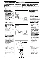
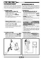
F. 1

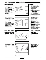
F. 2

IL MOTORE NON SI AVVIA O SI AVVIA CON

IL MOTORE NON SI AVVIA O SI AVVIA CON

IL MOTORE NON SI AVVIA O SI AVVIA CON

IL MOTORE NON SI AVVIA O SI AVVIA CON

IL MOTORE NON SI AVVIA O SI AVVIA CON
DIFFICOLTÀ

DIFFICOLTÀ

DIFFICOLTÀ

DIFFICOLTÀ

DIFFICOLTÀ

• Avviare il motore senza intervenire sulla manopo-

la dell’acceleratore.

• Regolare il minimo a circa 1.400 giri/1’.

1.400 giri/1’.

1.400 giri/1’.

1.400 giri/1’.

1.400 giri/1’.

• Regolare la vite aria carburatore svitandola di

1½ giro ± ¼.

1½ giro ± ¼.

1½ giro ± ¼.

1½ giro ± ¼.

1½ giro ± ¼.

VERIFICA STARTER

VERIFICA STARTER

VERIFICA STARTER

VERIFICA STARTER

VERIFICA STARTER
ELETTRICO AUTOMATICO

ELETTRICO AUTOMATICO

ELETTRICO AUTOMATICO

ELETTRICO AUTOMATICO

ELETTRICO AUTOMATICO
a) Verificare l’alimentazione, col-

legando il tester (AC 20V) 

tester (AC 20V) 

tester (AC 20V) 

tester (AC 20V) 

tester (AC 20V) al

connettore del cablaggio (F. 1).
- Avviare il motore a circa

5.000 giri/1’.

5.000 giri/1’.

5.000 giri/1’.

5.000 giri/1’.

5.000 giri/1’.

- Terminale (+) 

 tester

terminale  giallo/verde

giallo/verde

giallo/verde

giallo/verde

giallo/verde.

- Terminale (-) 

 tester

terminale  nero

nero

nero

nero

nero.

- La tensione deve risultare:

12 Volt.

12 Volt.

12 Volt.

12 Volt.

12 Volt.

- Fuori specifica: cavo giallo/

giallo/

giallo/

giallo/

giallo/

verde

verde

verde

verde

verde o cavo nero

nero

nero

nero

nero interrotto.

- Verifica cavo nero (mas-

Verifica cavo nero (mas-

Verifica cavo nero (mas-

Verifica cavo nero (mas-

Verifica cavo nero (mas-
sa):

sa):

sa):

sa):

sa):  collegare tester

 tester

 tester

 tester

 tester

(((((

Ω 

Ω 

Ω 

Ω 

Ω 

x 1)

x 1)

x 1)

x 1)

x 1) al connettore del ca-

blaggio come segue (F. 2):

- Terminale (+) 

 tester

terminale nero

 nero

 nero

 nero

 nero.

- Terminale (-) 

 tester

a massa telaio.

- Non c’è continuità: cavo

nero

nero

nero

nero

nero interrotto. Riparare cre-
ando un ponte con un cavet-
to tra connettore e massa te-
laio.

- C’è continuità: cavo giallo/

 giallo/

 giallo/

 giallo/

 giallo/

verde

verde

verde

verde

verde interrotto riparare cre-
ando un ponte con un cavet-
to tra cavo giallo/verde

giallo/verde

giallo/verde

giallo/verde

giallo/verde in-

serito nel connettore dello
starter e uno dei cavi verdi
(uno qualsiasi) inserito nel
connettore del volano (vedi
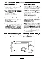
schema elettrico).

- Come da specifica: prose-

guire la ricerca.

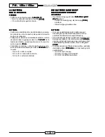
F. 3

b) Verificare l’avanzamento

Verificare l’avanzamento

Verificare l’avanzamento

Verificare l’avanzamento

Verificare l’avanzamento
dell’ago 

dell’ago 

dell’ago 

dell’ago 

dell’ago (F. 3):
- collegare ad una batteria

(12V

12V

12V

12V

12V) i cavetti dello starter

e verificare nel tempo il va-
riare dell’altezza del piston-
cino; nel caso non subisse
variazioni nell’arco di circa
5 minuti, sostituire lo star-
ter.

~ mm 4

~ mm 4

~ mm 4

~ mm 4

~ mm 4

F18 - 125

F18 - 125

F18 - 125

F18 - 125

F18 - 125cc / 150cc

cc / 150cc

cc / 150cc

cc / 150cc

cc / 150cc

DER MOTOR

DER MOTOR

DER MOTOR

DER MOTOR

DER MOTOR LÄUFT NICHT AN ODER ER

LÄUFT NICHT AN ODER ER

LÄUFT NICHT AN ODER ER

LÄUFT NICHT AN ODER ER

LÄUFT NICHT AN ODER ER

LÄUFT MIT SCHWIERIGKEIT AN

LÄUFT MIT SCHWIERIGKEIT AN

LÄUFT MIT SCHWIERIGKEIT AN

LÄUFT MIT SCHWIERIGKEIT AN

LÄUFT MIT SCHWIERIGKEIT AN

• Den Motor in Betrieb setzen ohne den Gasgriff zu

betätigen.

• Den Leerlauf zu 1.400 Upm 

1.400 Upm 

1.400 Upm 

1.400 Upm 

1.400 Upm regulieren.

• Die Schraube Vergaser-Luft um 1½ Drehungen ± ¼

 1½ Drehungen ± ¼

 1½ Drehungen ± ¼

 1½ Drehungen ± ¼

 1½ Drehungen ± ¼

losschrauben.

PRÜFUNG DES AUTOMATISCHEN

PRÜFUNG DES AUTOMATISCHEN

PRÜFUNG DES AUTOMATISCHEN

PRÜFUNG DES AUTOMATISCHEN

PRÜFUNG DES AUTOMATISCHEN
ELEKTR.STARTERS

ELEKTR.STARTERS

ELEKTR.STARTERS

ELEKTR.STARTERS

ELEKTR.STARTERS

a) Die elektrische Versorgung

überprüfen. Das Vielfachmessgerät

Vielfachmessgerät

Vielfachmessgerät

Vielfachmessgerät

Vielfachmessgerät

(AC 20V) 

(AC 20V) 

(AC 20V) 

(AC 20V) 

(AC 20V) an den
Verdrahtungsverbinder
(Abb. 1) anschliessen.
- Den Motor mit ca. 5.000 UpM

5.000 UpM

5.000 UpM

5.000 UpM

5.000 UpM

anlaufen.

- Endverschluss Vielfachmessgerät (+)

  gelber

gelber

gelber

gelber

gelber/grünen

/grünen

/grünen

/grünen

/grünen  Endverschluss.

- Endverschluss Vielfachmessgerät (-)

  schwarzer

schwarzer

schwarzer

schwarzer

schwarzer  Endverschluss

- Spannung soll 12 Volt 

 12 Volt 

 12 Volt 

 12 Volt 

 12 Volt sein.

- Außerhalb Spezifikation: gelbes

gelbes

gelbes

gelbes

gelbes/////

grünes Kabel

grünes Kabel

grünes Kabel

grünes Kabel

grünes Kabel oder  schwarzes

schwarzes

schwarzes

schwarzes

schwarzes

Kabel unterbrochen.

- Prüfung des schwarzen Kabels

Prüfung des schwarzen Kabels

Prüfung des schwarzen Kabels

Prüfung des schwarzen Kabels

Prüfung des schwarzen Kabels
(Erde):

(Erde):

(Erde):

(Erde):

(Erde): das Vielfachmessgerät

das Vielfachmessgerät

das Vielfachmessgerät

das Vielfachmessgerät

das Vielfachmessgerät

(((((

Ω 

Ω 

Ω 

Ω 

Ω 

x 1)

x 1)

x 1)

x 1)

x 1) an den

Verdrahtungsverbinder wie folgt
anschliessen (Abb. 2):

- Endverschluss Vielfachmessgerät

(+) 

  schwarzer

schwarzer

schwarzer

schwarzer

schwarzer Endverschluss

- Endverschluss Vielfachmessgerät

(-) 

   am Fahrgestell geerdet.

- Keiner Stromdurchgang:

schwarzes

schwarzes

schwarzes

schwarzes

schwarzes Kabel unterbrochen.
Durch Überbrückung mit einem
Kabel zwischen Verbinder und
Fahrgestellerde instandsetzen.

- Stromdurchgang: gelbes/grünes

gelbes/grünes

gelbes/grünes

gelbes/grünes

gelbes/grünes

Kabel unterbrochen. Durch
Überbrückung mit einem Kabel
zwischen dem gelben/grünem

gelben/grünem

gelben/grünem

gelben/grünem

gelben/grünem

Kabel, das am Starterverbinder
angeschlossen ist, und einem der
grünen  Kabeln (irgendeinem), das
am Schwungradverbinder
angeschlossen ist (siehe
Schaltplan) .

- Innerhalb Spezifikation:

weitersuchen.

b) Die Nadelbewegung prüfen

Die Nadelbewegung prüfen

Die Nadelbewegung prüfen

Die Nadelbewegung prüfen

Die Nadelbewegung prüfen
(Abb. 3):
- Die Kabel des Starters an

eine Batterie (12V

12V

12V

12V

12V)

anschliessen und die
Änderung der Kolbenhöhe
prüfen; sind keine
Änderungen in 5 Minuten
nicht festgestellt werden,
den Starter ersetzen.

Summary of Contents for F18 WARRIOR

Page 1: ...YSTEM TROUBLESHOOTING ELECTRIC SYSTEM TROUBLESHOOTING ELECTRIC SYSTEM TROUBLESHOOTING ELECTRIC SYSTEM TROUBLESHOOTING ELECTRIC SYSTEM TROUBLESHOOTING IDENTIFICATION DES PANNES DANS L INSTALLATION ELEC...

Page 2: ...No part of this publication whether text or illustrations may be reproduced may be reproduced may be reproduced may be reproduced may be reproduced or circulated without the prior written permission f...

Page 3: ...icina Manuale officina Manuale officina Manuale officina Manuale officina del motore del motore del motore del motore del motore dal Catalogo ricambi Catalogo ricambi Catalogo ricambi Catalogo ricambi...

Page 4: ...our hands The table of contents table of contents table of contents table of contents table of contents will be duly updated in case of the insertion of new pages causing difficulty in the rational co...

Page 5: ...E PAGINE AGGIUNTIVE PAGINE AGGIUNTIVE PAGINE AGGIUNTIVE Eventuali pagine aggiuntive porteranno l ultimo numero della loro sezione d appartenenza seguito da una A A A A A e la nuova data nuova data nuo...

Page 6: ...uido de una A A A A A y la nueva fecha nueva fecha nueva fecha nueva fecha nueva fecha de edici n Hinweis Hinweis Hinweis Hinweis Hinweis Falls keinerlei Angabe gemacht wurde an der Stelle des K stche...

Page 7: ...y servicing Before any servicing Before any servicing Before any servicing Before any servicing make sure that the motor bike is perfectly stable The front wheel should preferably be anchored to the e...

Page 8: ...strumentenbrett dashboard does sur le tableau de en el salpicadero 32 non funziona funktioniert nicht not work bord nemarchepas no funciona Motorino Der motor The motor of the Le moteur du rotor Motor...

Page 9: ...L UFT NICHT AN ODER ER L UFT NICHT AN ODER ER L UFT NICHT AN ODER ER L UFT NICHT AN ODER ER L UFT NICHT AN ODER ER L UFT MIT SCHWIERIGKEIT AN L UFT MIT SCHWIERIGKEIT AN L UFT MIT SCHWIERIGKEIT AN L UF...

Page 10: ...000 tours mn Borne testeur cosse cosse cosse cosse cosse jaune vert jaune vert jaune vert jaune vert jaune vert Borne testeur cosse noire cosse noire cosse noire cosse noire cosse noire La tension doi...

Page 11: ...assa massa massa massa massa x 1K x 1K x 1K x 1K x 1K c Pr fung des Pr fung des Pr fung des Pr fung des Pr fung des Schwungmagnetz nders Schwungmagnetz nders Schwungmagnetz nders Schwungmagnetz nders...

Page 12: ...0 16 et 1 0 entre 0 16 et 1 0 entre 0 16 et 1 0 entre 0 16 et 1 0 entre 0 16 et 1 0 F 6 D connecter le connecteur deux voies et connecter le testeur en OHM F 5 Borne testeur cosse jaune bleue jaune bl...

Page 13: ...SE DUCATI utilizzando l adattatore cod 01729500 cod 01729500 cod 01729500 cod 01729500 cod 01729500 3 3 3 3 3 3 Widerstand der Widerstand der Widerstand der Widerstand der Widerstand der sekund ren Wi...

Page 14: ...K from 7 6 to 9 6 K with spark plug cap F 8 e Check of the electronic Check of the electronic Check of the electronic Check of the electronic Check of the electronic control unit control unit control...

Page 15: ...n c continuit sostitui re il commutatore destro C continuit proseguire la ricerca F18 125 F18 125 F18 125 F18 125 F18 125cc 150cc cc 150cc cc 150cc cc 150cc cc 150cc DER MOTOR L UFT NUR MIT DER MOTOR...

Page 16: ...necessary fill it with distilled water 2 Check if sulphation marks are present 3 If necessary replace the battery b Starting motor check Starting motor check Starting motor check Starting motor check...

Page 17: ...1 1 1 1 1 3 3 3 3 3 2 2 2 2 2 F18 125 F18 125 F18 125 F18 125 F18 125cc 150cc cc 150cc cc 150cc cc 150cc cc 150cc d Pr fung des Anlassrelais Abb 11 Pr fung des Anlassrelais Abb 11 Pr fung des Anlassre...

Page 18: ...x 1 x 1 x 1 x 1 x 1 du c ble rouge du c ble rouge du c ble rouge du c ble rouge du c ble rouge entre la cosse introduite dans les interrupteurs stop et la cosse introduite dans le relais de d marrage...

Page 19: ...ton folgen dann die Verbindung ausschalten und das aus der Verdrahtung Erde herauskommende Kabel an das Fahrgestell anliegen Abb 12 A Der Motor h lt an Der Motor h lt an Der Motor h lt an Der Motor h...

Page 20: ...white black black black black black terminal Place the key on OFF No continuity replace the key commutator Continuity continue searching Check the ground black cable Check the ground black cable Chec...

Page 21: ...ompleta 12 5 volt necessaria la ricarica 12 0 volt sostituire la batteria DIE BATTERIE KANN NICHT DIE BATTERIE KANN NICHT DIE BATTERIE KANN NICHT DIE BATTERIE KANN NICHT DIE BATTERIE KANN NICHT NACHGE...

Page 22: ...idiendo la tensi n en circuito abierto es decir cuando el borne positivo est desconectado Conectar un volt metro a los bornes de la bater a el valor que resulte debe alcanzar al menos los 12 8 volt 12...

Page 23: ...nnung eine geladene Pr fung der Ladungsspannung eine geladene Pr fung der Ladungsspannung eine geladene Batterie verwenden Batterie verwenden Batterie verwenden Batterie verwenden Batterie verwenden D...

Page 24: ...tor encendido 13 volt 13 volt 13 volt 13 volt 13 volt 13 volt 13 volt 13 volt 13 volt 13 volt 12 7 volt 0 3 volt 12 7 volt 0 3 volt 12 7 volt 0 3 volt 12 7 volt 0 3 volt 12 7 volt 0 3 volt Valores no...

Page 25: ...orrente continua in uscita riparare vedi schema elettrico SCHL SSELUMSCHALTER AUF ON TAFEL 0 SCHL SSELUMSCHALTER AUF ON TAFEL 0 SCHL SSELUMSCHALTER AUF ON TAFEL 0 SCHL SSELUMSCHALTER AUF ON TAFEL 0 SC...

Page 26: ...brown brown brown cable terminal Turn the commutator key on ON No continuity replace the key commutator Continuity continue searching C C C C C Check the continuity of the blue Check the continuity o...

Page 27: ...cerca SENSOR SENSOR SENSOR SENSOR SENSOR KRAFTSTOFFSTAND KRAFTSTOFFSTAND KRAFTSTOFFSTAND KRAFTSTOFFSTAND KRAFTSTOFFSTAND Der Sensor f r den Kraftstoffstand befindet sich an der Vorderseite des Tanks U...

Page 28: ...auge ne se d pla ce pas poursuivre la recherche DETECTOR NIVEL DETECTOR NIVEL DETECTOR NIVEL DETECTOR NIVEL DETECTOR NIVEL CARBURANTE CARBURANTE CARBURANTE CARBURANTE CARBURANTE El detector nivel carb...

Page 29: ...le cavo grigio grigio grigio grigio grigio Lancetta indicatore non si sposta sostituire il cruscot to completo D D D D D Pr fung des Instrumentenbrettanzeigers Pr fung des Instrumentenbrettanzeigers P...

Page 30: ...ck of the dashboard Check of the dashboard Check of the dashboard indicator indicator indicator indicator indicator By means of two cables supply voltage directly to the six way connector of the dashb...

Page 31: ...el cavo grigio rosso grigio rosso grigio rosso grigio rosso grigio rosso e riparare F 20 PR FUNG DER RESERVELAMPE PR FUNG DER RESERVELAMPE PR FUNG DER RESERVELAMPE PR FUNG DER RESERVELAMPE PR FUNG DER...

Page 32: ...is rojo gris rojo gris rojo gris rojo y el cable negro negro negro negro negro Luz encendida sustituir la sonda gasolina La luz no se enciende continuar la b squeda Controlar la continuidad del cable...

Page 33: ...URANZEIGER DER TEMPERATURANZEIGER DER TEMPERATURANZEIGER auf dem auf dem auf dem auf dem auf dem Instrumentenbrett Instrumentenbrett Instrumentenbrett Instrumentenbrett Instrumentenbrett FUNKTIONIERT...

Page 34: ...indicador temperatura Control indicador temperatura Control indicador temperatura salpicadero salpicadero salpicadero salpicadero salpicadero Llevar tensi n con dos cables directamente al conector de...

Page 35: ...n dem Endverschluss der am Thermoschalter angeschlossen ist und dem Endverschluss der am 2 Weg L fterverbinder angeschlossen ist pr fen Stromdurchgang Keine Erdung im schwarzen Kabel des 2 Weg L fterv...

Page 36: ...ck of the voltage to the fan Check of the voltage to the fan motor motor motor motor motor Disconnect both terminals from the thermal switch blue and yellow blue and yellow blue and yellow blue and ye...

Page 37: ...N Non c continuit sostituire il commutatore sinistro C continuit proseguire la ricerca DAS HORN FUNKTIONIERT NICHT DAS HORN FUNKTIONIERT NICHT DAS HORN FUNKTIONIERT NICHT DAS HORN FUNKTIONIERT NICHT D...

Page 38: ...RUPTOR HORN CONTROL INTERRUPTOR HORN Desconectar el conector de nueve v as del conmutador izquierdo desmontar el cubremanillar Controlar la continuidad tester tester tester tester tester x 1 x 1 x 1 x...

Page 39: ...stro Riparare vedi schema elettrico PR FUNG DER SPANNUNG AN DIE PR FUNG DER SPANNUNG AN DIE PR FUNG DER SPANNUNG AN DIE PR FUNG DER SPANNUNG AN DIE PR FUNG DER SPANNUNG AN DIE HORN ENDVERSCHL SSE HORN...

Page 40: ...nja Llave conmutador en ON Apretar el bot n HORN Tensi n 12 volt sustituir el claxon Falta tensi n continuar la b squeda Controlar la tensi n al cable azul Controlar la tensi n al cable azul Controlar...

Page 41: ...rci continuit Non c continuit sostituire il commutatore C continuit proseguire la ricerca DIE RICHTUNGSANZEIGER BLINKEN NICHT DIE RICHTUNGSANZEIGER BLINKEN NICHT DIE RICHTUNGSANZEIGER BLINKEN NICHT DI...

Page 42: ...INTERRUPTOR INDICADOR DE DIRECCION CONTROL INTERRUPTOR INDICADOR DE DIRECCION Desconectar el conector de nueve v as del conmutador izquierdo tester tester tester tester tester x 1 x 1 x 1 x 1 x 1 F 27...

Page 43: ...ne nero interrotto Riparare vedi schema elettrico PR FUNGDERSPANNUNGAN PR FUNGDERSPANNUNGAN PR FUNGDERSPANNUNGAN PR FUNGDERSPANNUNGAN PR FUNGDERSPANNUNGAN DIE AUSSETZUNG A DIE AUSSETZUNG A DIE AUSSETZ...

Page 44: ...nsi n 0 el circuito entre conmutador llave y conector intermitencia es defectuoso Reparar el cable azul azul azul azul azul Tensi n 12 volt continuar la b squeda Controlar la continuidad del Controlar...

Page 45: ...PANNUNG PR FUNG DER SPANNUNG AN DEN LAMPENFASSUNG AN DEN LAMPENFASSUNG AN DEN LAMPENFASSUNG AN DEN LAMPENFASSUNG AN DEN LAMPENFASSUNG SVERBINDER DER SVERBINDER DER SVERBINDER DER SVERBINDER DER SVERBI...

Page 46: ...0V 20V 20V Tester terminal green green green green green cable terminal Tester terminal black black black black black cable terminal Change over switch key on ON Position the switch on right indicator...

Page 47: ...ale cavo nero nero nero nero nero Chiave commutatore in ON Azionare la leva del freno dx o sx La tensione riscontrata deve essere di 12 volt 12 volt 12 volt 12 volt 12 volt Fuori specifica cavo nero n...

Page 48: ...PAS S ALLUMENT PAS S ALLUMENT PAS S ALLUMENT PAS S ALLUMENT PAS a Contr ler l ampoule et la douille Contr ler l ampoule et la douille Contr ler l ampoule et la douille Contr ler l ampoule et la douil...

Page 49: ...MS PR FUNG DES LICHTSYSTEMS PR FUNG DES LICHTSYSTEMS FERNLICHT UND FERNLICHTLAMPE LEUCHTEN NICHT AUF A FERNLICHT UND FERNLICHTLAMPE LEUCHTEN NICHT AUF A FERNLICHT UND FERNLICHTLAMPE LEUCHTEN NICHT AUF...

Page 50: ...DC 20V tester DC 20V al conector del faro y de la luz indicadora FARO FARO FARO FARO FARO Terminal tester terminal cable blanco negro blanco negro blanco negro blanco negro blanco negro Terminal test...

Page 51: ...lampadina e lo stampato della pista cruscotto nel caso sostituire FERNLICHTLAMPE FERNLICHTLAMPE FERNLICHTLAMPE FERNLICHTLAMPE FERNLICHTLAMPE Abb Abb Abb Abb Abb 35 35 35 35 35 Endverschluss Vielfachme...

Page 52: ...e negro negro negro negro negro Llave conmutador en ON Situar el conmutador luces en Situar el conmutador izquierdo en deslumbrante La tensi n debe ser de 12 volt 12 volt 12 volt 12 volt 12 volt Fuera...

Page 53: ...are o sostituire ABBLENDLICHT UND ABBLENDLICHTLAMPE LEUCHTEN NICHT AUF ABBLENDLICHT UND ABBLENDLICHTLAMPE LEUCHTEN NICHT AUF ABBLENDLICHT UND ABBLENDLICHTLAMPE LEUCHTEN NICHT AUF ABBLENDLICHT UND ABBL...

Page 54: ...et de la lampe t moin PHARE PHARE PHARE PHARE PHARE F 36 F 36 F 36 F 36 F 36 Borne testeur cosse c ble blanc bleu blanc bleu blanc bleu blanc bleu blanc bleu Borne testeur cosse c ble noir noir noir...

Page 55: ...F18 125 F18 125 F18 125 F18 125cc 150cc cc 150cc cc 150cc cc 150cc cc 150cc ABBLENDLICHTLAMPE ABBLENDLICHTLAMPE ABBLENDLICHTLAMPE ABBLENDLICHTLAMPE ABBLENDLICHTLAMPE Endverschluss Vielfachmessger t w...

Page 56: ...x sur Mettre le commutateur gauche sur codes La tension doit tre de 12 volts 12 volts 12 volts 12 volts 12 volts Non conforme aux indications le circuit entre le connecteur quatre voies introduit dans...

Page 57: ...seguire la ricerca F 38 DIE BELEUCHTUNG DES INSTRUMENTENBRETTS DIE BELEUCHTUNG DES INSTRUMENTENBRETTS DIE BELEUCHTUNG DES INSTRUMENTENBRETTS DIE BELEUCHTUNG DES INSTRUMENTENBRETTS DIE BELEUCHTUNG DES...

Page 58: ...us de la lumi re du tableau de bord la lumi re du tableau de bord la lumi re du tableau de bord la lumi re du tableau de bord la lumi re du tableau de bord la lumi re du feu arri re non plus ne marche...

Page 59: ...fung der Spannung am 6 Weg Verbinder des In Pr fung der Spannung am 6 Weg Verbinder des In Pr fung der Spannung am 6 Weg Verbinder des In Pr fung der Spannung am 6 Weg Verbinder des In strumentenbrett...

Page 60: ...rminal cable negro negro negro negro negro Llave conmutador en ON Interruptor luces conmutador derecho en posici n o La tensi n debe ser de 12 volt 12 volt 12 volt 12 volt 12 volt Como el valor especi...

Page 61: ...CHTAUF DASLICHTDERHINTERLEUCHTELEUCHTETNICHTAUF DASLICHTDERHINTERLEUCHTELEUCHTETNICHTAUF DASLICHTDERHINTERLEUCHTELEUCHTETNICHTAUF DASLICHTDERHINTERLEUCHTELEUCHTETNICHTAUF A A A A A Die Lampe und die L...

Page 62: ...ts 12 volts 12 volts Conformeauxindications lecircuit duc blageprincipalestenbon tat de marche Le c blage du feu arri re est d fectueux changer our parer Non conforme aux indications poursuivre la rec...

Page 63: ...62 11 00 NOTES NOTES NOTES NOTES NOTES...

Reviews: