35
11/00
F18 - 125
F18 - 125
F18 - 125
F18 - 125
F18 - 125cc / 150cc
cc / 150cc
cc / 150cc
cc / 150cc
cc / 150cc
THE MOTOR OF THE
THE MOTOR OF THE
THE MOTOR OF THE
THE MOTOR OF THE
THE MOTOR OF THE
RADIATOR FAN DOES NOT
RADIATOR FAN DOES NOT
RADIATOR FAN DOES NOT
RADIATOR FAN DOES NOT
RADIATOR FAN DOES NOT
WORK
WORK
WORK
WORK
WORK
A)
A)
A)
A)
A) Check of the fan motor
Check of the fan motor
Check of the fan motor
Check of the fan motor
Check of the fan motor
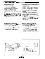
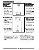
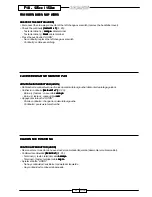
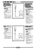
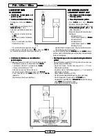
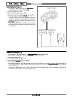
• Disconnect the fan connector and
supply voltage directly by means
of two cables (F. 23):
- Battery terminal (+): red
red
red
red
red cable
terminal.
- Battery terminal (-): black
black
black
black
black cable
terminal.
-
The fan motor does not run:
replace the motor.
-
The fan motor runs: continue
searching.
LE MOTEUR DU ROTOR DE
LE MOTEUR DU ROTOR DE
LE MOTEUR DU ROTOR DE
LE MOTEUR DU ROTOR DE
LE MOTEUR DU ROTOR DE
VENTILATION RADIATEUR
VENTILATION RADIATEUR
VENTILATION RADIATEUR
VENTILATION RADIATEUR
VENTILATION RADIATEUR
NE MARCHE PAS
NE MARCHE PAS
NE MARCHE PAS
NE MARCHE PAS
NE MARCHE PAS
A) Contrôle du moteur du rotor de
A) Contrôle du moteur du rotor de
A) Contrôle du moteur du rotor de
A) Contrôle du moteur du rotor de
A) Contrôle du moteur du rotor de
ventilation
ventilation
ventilation
ventilation
ventilation
• Déconnecter le connecteur du rotor
de ventilation et amener la tension
directement par l’intermédiaire de
deux câbles (F. 23) :
- Borne (+) batterie : cosse câble
rouge.
rouge.
rouge.
rouge.
rouge.
- Borne (-) batterie : cosse câble
noir
noir
noir
noir
noir.
- Le moteur du rotor de ventilation
ne tourne pas : changer le moteur
du rotor.
- Le moteur du rotor de ventilation
tourne : poursuivre la recherche.
B)
B)
B)
B)
B) Contrôle de la tension au moteur
Contrôle de la tension au moteur
Contrôle de la tension au moteur
Contrôle de la tension au moteur
Contrôle de la tension au moteur
du rotor de ventilation
du rotor de ventilation
du rotor de ventilation
du rotor de ventilation
du rotor de ventilation
• Déconnecter les deux cosses de
l’interrupteur thermique (câble bleu
câble bleu
câble bleu
câble bleu
câble bleu
et câble jaune
et câble jaune
et câble jaune
et câble jaune
et câble jaune).
• Créer un pontet au moyen d’un
câbleau entre les deux câbles (F. 24).
• Tourner la clef du démarreur sur “ON” :
- Le moteur du rotor de ventilation
tourne : changer l’interrupteur
thermique.
- Le moteur du rotor de ventilation
ne tourne pas : poursuivre la
recherche.
C) Contrôler la continuité du câble
C) Contrôler la continuité du câble
C) Contrôler la continuité du câble
C) Contrôler la continuité du câble
C) Contrôler la continuité du câble
bleu (testeur OHM)
bleu (testeur OHM)
bleu (testeur OHM)
bleu (testeur OHM)
bleu (testeur OHM) entre la cosse
introduite dans le porte-fusible de
10 AH et la cosse introduite dans
l’interrupteur thermique.
- Continuité: poursuivre la
recherche.
D) Contrôler la continuité du câble
D) Contrôler la continuité du câble
D) Contrôler la continuité du câble
D) Contrôler la continuité du câble
D) Contrôler la continuité du câble
jaune (testeur OHM)
jaune (testeur OHM)
jaune (testeur OHM)
jaune (testeur OHM)
jaune (testeur OHM) entre la cosse
introduite dans l’interrupteur
thermique et la cosse introduite
dans le connecteur à deux voies
du rotor de ventilation.
- Continuité : absence de masse au
câble noir du connecteur à deux
voies du rotor de ventilation.
Réparer en créant un pontet au
moyen d’un cableau entre la cosse
noire et un point à masse du
châssis.
B)
B)
B)
B)
B) Check of the voltage to the fan
Check of the voltage to the fan
Check of the voltage to the fan
Check of the voltage to the fan
Check of the voltage to the fan
motor
motor
motor
motor
motor
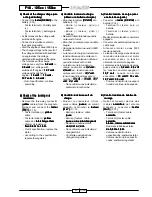
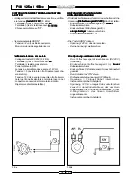
• Disconnect both terminals from the
thermal switch (blue and yellow
blue and yellow
blue and yellow
blue and yellow
blue and yellow
cable
cable
cable
cable
cable).
• Create a bridge with a cable between
both cables (F. 24).
• Turn the commutator key on “ON”:
- The fan motor runs: replace the
thermal switch.
- The fan motor does not run:
continue searching.
C)
C)
C)
C)
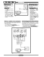
C) Check the continuity of the blue
Check the continuity of the blue
Check the continuity of the blue
Check the continuity of the blue
Check the continuity of the blue
cable (tester OHM)
cable (tester OHM)
cable (tester OHM)
cable (tester OHM)
cable (tester OHM) between the
terminal, which is connected to the
fuse holder 10 AH and the terminal
which is connected to the thermal
switch.
- Continuity: continue searching.
D)
D)
D)
D)
D) Check the continuity of the yel-
Check the continuity of the yel-
Check the continuity of the yel-
Check the continuity of the yel-
Check the continuity of the yel-
low cable (tester OHM)
low cable (tester OHM)
low cable (tester OHM)
low cable (tester OHM)
low cable (tester OHM) between
the terminal, which is connected to
the thermal switch and the termi-
nal, which is connected to the 2-
way fan connector.
-
Continuity: no ground in the black
cable of the 2-way fan connector.
Repair by means of a bridge with
a cable between the black terminal
and a grounded point in the frame.
B)
B)
B)
B)
B) Controlar la tensión al motor
Controlar la tensión al motor
Controlar la tensión al motor
Controlar la tensión al motor
Controlar la tensión al motor
ventilador
ventilador
ventilador
ventilador
ventilador
• Desconectar los dos terminales del
interuptor térmico (cable azul y
cable azul y
cable azul y
cable azul y
cable azul y
cable amarillo
cable amarillo
cable amarillo
cable amarillo
cable amarillo).
• Hacer un puente con un cable entre
los dos cables (F. 24).
• Situar la llave del conmutador en
“ON”:
-
Motor ventilador no gira: sustituir
el interruptor térmico.
-
Motor ventilador gira: continuar la
búsqueda.
C)
C)
C)
C)
C) Controlar la continuidad del
Controlar la continuidad del
Controlar la continuidad del
Controlar la continuidad del
Controlar la continuidad del
cable azul (tester OHM)
cable azul (tester OHM)
cable azul (tester OHM)
cable azul (tester OHM)
cable azul (tester OHM) entre el
terminal conectado al portafusible
de 10 AH y el terminal conectado
al interruptor térmico.
-
Hay continuidad: continuar la
búsqueda.
D)
D)
D)
D)
D) Controlar la continuidad del
Controlar la continuidad del
Controlar la continuidad del
Controlar la continuidad del
Controlar la continuidad del
cable amarillo (tester OHM)
cable amarillo (tester OHM)
cable amarillo (tester OHM)
cable amarillo (tester OHM)
cable amarillo (tester OHM)
entre el terminal conectado al
interruptor térmico y el terminal
conectado al conector de dos vías
del ventilador.
-
Hay continuidad : falta la masa al
cable negro del conector de dos
vías del ventilador. Reparar
haciendo un puente con un cable
entre terminal negro y un punto en
masa del chasís.
MOTOR VENTILADOR
MOTOR VENTILADOR
MOTOR VENTILADOR
MOTOR VENTILADOR
MOTOR VENTILADOR
RADIADOR NO
RADIADOR NO
RADIADOR NO
RADIADOR NO
RADIADOR NO
FUNCIONA
FUNCIONA
FUNCIONA
FUNCIONA
FUNCIONA
A)
A)
A)
A)
A) Control motor ventilador
Control motor ventilador
Control motor ventilador
Control motor ventilador
Control motor ventilador
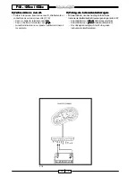
• Desconectar el conector del
ventilador y llevar la tensión
directamente a través de dos
cables (F. 23):
- Borne (+) batería: terminal cable
rojo
rojo
rojo
rojo
rojo.
- Borne (-) batería: terminal ceble
negro
negro
negro
negro
negro.
-
Motor ventilador no gira: sustituir
el motor.
-
Motor ventilador gira: continuar la
búsqueda.


