23
11/00
A)
A)
A)
A)
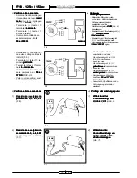
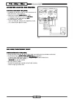
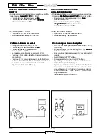
A) Check of the charge voltage (use
Check of the charge voltage (use
Check of the charge voltage (use
Check of the charge voltage (use
Check of the charge voltage (use
a charged battery)
a charged battery)
a charged battery)
a charged battery)
a charged battery)
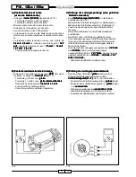
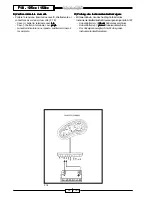
• Connect the tester (DC 20V)
tester (DC 20V)
tester (DC 20V)
tester (DC 20V)
tester (DC 20V) to the
battery (F.14):
- Tester terminal (+): battery pole
(+)
- Tester terminal (-): battery pole
(-)
• At first measure the voltage with
switched off engine.
• Connect a revolution counter to
the spark plug cable.
• Start the engine at about 5000 rpm.
• The charge voltage is the result of
the voltage obtained with switched
on engine less the voltage
obtained with switched off engine.
• The tolerance of the charge
voltage can vary from 0.2 volts
0.2 volts
0.2 volts
0.2 volts
0.2 volts to
2.5 volts
2.5 volts
2.5 volts
2.5 volts
2.5 volts (i.e. voltage with
switched off engine = 12.7 volts
12.7 volts
12.7 volts
12.7 volts
12.7 volts -
voltage with switched on
engine = 13 volts
13 volts
13 volts
13 volts
13 volts
→
13 volts -
13 volts -
13 volts -
13 volts -
13 volts -
12.7 volts = 0.3 volts
12.7 volts = 0.3 volts
12.7 volts = 0.3 volts
12.7 volts = 0.3 volts
12.7 volts = 0.3 volts)
-
Out of specification: continue
searching.
B)
B)
B)
B)
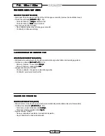
B) Check of the loading coil
Check of the loading coil
Check of the loading coil
Check of the loading coil
Check of the loading coil
resistance
resistance
resistance
resistance
resistance
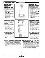
• Remove the three-way connector
(yellow
yellow
yellow
yellow
yellow cables) from the magneto
flywheel and connect the tester
tester
tester
tester
tester
(((((
Ω
Ω
Ω
Ω
Ω
x 1)
x 1)
x 1)
x 1)
x 1) (F. 15):
- Tester terminal (+): yellow
yellow
yellow
yellow
yellow
cable
- Tester terminal (-): yellow
yellow
yellow
yellow
yellow
cable and interchange them
interchange them
interchange them
interchange them
interchange them
- Stator coil resistance:
from 0.6
from 0.6
from 0.6
from 0.6
from 0.6
Ω
Ω
Ω
Ω
Ω
to 1.6
to 1.6
to 1.6
to 1.6
to 1.6
Ω.
Ω.
Ω.
Ω.
Ω.
-
Out of specification: replace the
stator.
-
According to the specification:
replace the regulator.
A)
A)
A)
A)
A) Control tensión de carga (usar
Control tensión de carga (usar
Control tensión de carga (usar
Control tensión de carga (usar
Control tensión de carga (usar
una batería cargada)
una batería cargada)
una batería cargada)
una batería cargada)
una batería cargada)
• Conectar el tester (DC 20V)
tester (DC 20V)
tester (DC 20V)
tester (DC 20V)
tester (DC 20V) a la
batería (F. 14):
- Terminal (+) tester: polo (+)
batería
- Terminal (-) tester: polo (-)
batería
• Medir primero la tensión con el motor
apagado.
• Conectar un cuentarrevoluciones al
cable bujía.
• Arrancar el motor a unas 5000
revoluciones/min.
• La tensión de carga viene dada por
la tensión obtenida con el motor
encendido, menos la tensión
obtenida con el motor apagado.
• La tolerancia de la tensión de carga,
puede variar de 0,2 volt
0,2 volt
0,2 volt
0,2 volt
0,2 volt a 2,5 volt
2,5 volt
2,5 volt
2,5 volt
2,5 volt
(ej.: tensión con motor apagado =
12,7 volt
12,7 volt
12,7 volt
12,7 volt
12,7 volt - tensión con motor
encendido = 13 volt
13 volt
13 volt
13 volt
13 volt
→
→
→
→
→
13 volt -
13 volt -
13 volt -
13 volt -
13 volt -
12,7 volt = 0,3 volt
12,7 volt = 0,3 volt
12,7 volt = 0,3 volt
12,7 volt = 0,3 volt
12,7 volt = 0,3 volt).
-
Valores no dentro de los especi-
ficados: continuar la búsqueda.
B)
B)
B)
B)
B) Control resistencia bobina de
Control resistencia bobina de
Control resistencia bobina de
Control resistencia bobina de
Control resistencia bobina de
recarga
recarga
recarga
recarga
recarga
• Quitar el conector de dos vías
(cables amarillos
amarillos
amarillos
amarillos
amarillos) del volante
magneto, y conectar el tester
tester
tester
tester
tester
(((((
Ω
Ω
Ω
Ω
Ω
x 1)
x 1)
x 1)
x 1)
x 1) (F. 15):
- Terminal (+) tester: cable
amarillo
amarillo
amarillo
amarillo
amarillo
- Terminal (-) tester: cable
amarillo
amarillo
amarillo
amarillo
amarillo
blanco, intercambiándolos
blanco, intercambiándolos
blanco, intercambiándolos
blanco, intercambiándolos
blanco, intercambiándolos
- Resistencia bobina estator:
da 0,6
da 0,6
da 0,6
da 0,6
da 0,6
Ω
Ω
Ω
Ω
Ω
a 1,6
a 1,6
a 1,6
a 1,6
a 1,6
Ω.
Ω.
Ω.
Ω.
Ω.
-
Valores no dentro de los
especificados: sustituir estator.
-
Valores dentro de los especifi-
cados: sustituir el regulador.
F18 - 125
F18 - 125
F18 - 125
F18 - 125
F18 - 125cc / 150cc
cc / 150cc
cc / 150cc
cc / 150cc
cc / 150cc
A)
A)
A)
A)
A) Contrôle tension de charge
Contrôle tension de charge
Contrôle tension de charge
Contrôle tension de charge
Contrôle tension de charge
(utiliser une batterie chargée)
(utiliser une batterie chargée)
(utiliser une batterie chargée)
(utiliser une batterie chargée)
(utiliser une batterie chargée)
• Brancher le testeur (CC 20V)
(CC 20V)
(CC 20V)
(CC 20V)
(CC 20V) à la
batterie (F. 14):
- Borne (+) testeur : pôle (+)
batterie
- Borne (-) testeur : pôle (-)
batterie
• Mesurer d’abord la tension quand le
moteur est à l’arrêt.
• Brancher un compte-tours au câble
bougie.
• Démarrer le moteur à environ 5000
tours/mn.
• La tension de charge provient de la
tension obtenue par le moteur en
marche, moins la tension obtenue
quand le moteur est à l’arrêt.
• La tolérance de la tension de
charge, peut varier de 0,2 volt
0,2 volt
0,2 volt
0,2 volt
0,2 volt à
2,5 volt
2,5 volt
2,5 volt
2,5 volt
2,5 volt (ex. : tension quand le
moteur est à l’arrêt = 12,7 volt
12,7 volt
12,7 volt
12,7 volt
12,7 volt -
tension quand le moteur est en
marche = 13 volt
13 volt
13 volt
13 volt
13 volt
→
13 volt
13 volt
13 volt
13 volt
13 volt - 12,7
12,7
12,7
12,7
12,7
volt
volt
volt
volt
volt = 0,3 volt
0,3 volt
0,3 volt
0,3 volt
0,3 volt).
- Non conforme aux indications :
poursuivre la recherche.
B)
B)
B)
B)
B) Contrôle résistance self de
Contrôle résistance self de
Contrôle résistance self de
Contrôle résistance self de
Contrôle résistance self de
charge
charge
charge
charge
charge
• Enlever le connecteur à trois
voies (câbles jaunes
jaunes
jaunes
jaunes
jaunes) du volant
magnéto, et brancher le testeur
testeur
testeur
testeur
testeur
(((((
Ω
Ω
Ω
Ω
Ω
x 1)
x 1)
x 1)
x 1)
x 1) (F. 15) :
- Borne (+) testeur : câble
jaune
jaune
jaune
jaune
jaune
- Borne (-) testeur : câble
jaune en les interchangeant
jaune en les interchangeant
jaune en les interchangeant
jaune en les interchangeant
jaune en les interchangeant
- Résistance bobine stator :
de 0,6
de 0,6
de 0,6
de 0,6
de 0,6
Ω
Ω
Ω
Ω
Ω
à 1,6
à 1,6
à 1,6
à 1,6
à 1,6
Ω.
Ω.
Ω.
Ω.
Ω.
- Non conforme aux indications :
changer stator.
- Conforme aux indications :
changer le régulateur.


