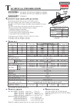
background image

P 9/ 13

R

epair

Fig. 11

(5)  Disassemble Brake mechanism as drawn in 

Fig. 11

.

1. Remove Bearing housing from Gear housing.

 Note

: Be sure that Link plate complete is in 

            “Saw chain brake activated” position.

            (See 

step 4

 in 

Fig. 10

).

            If not, set the Link plate to that position

            by gripping it with a water pump pliers.

Bearing housing

Link plate complete 
“Chain brake activated” position

Gear housing

Hook of Link plate complete

for hooking Brake band

Rib of Bearing housing 

3. Link plate complete section can now be disassembled

    by prying it up with a slotted screwdriver.

4. Remove Brake band from the opposite side of

    Bearing housing by unscrewing 4x12 Tapping

    screw. 

1R003

Link plate complete

Compression spring 9

Slotted screwdriver

Brake band

Flat washer 4

4x12 Tapping screw

[3] DISASSEMBLY/ASSEMBLY

[3]-3. Brake mechanism (cont.)

DISASSEMBLING

2. Using 1R003, pinch the hook of Link plate complete and the rib of Bearing housing to free Link plate

    from Bearing housing.

Summary of Contents for UC3050A

Page 1: ...omatic chain oiling Protection from electric shock Power supply cord m ft Model No UC3050A UC3051A UC3550A UC3551A UC4050A UC4051A UC4550A UC4551A 14 5 870 2 900 UK 10 32 8 Germany Sweden Reunion Chin...

Page 2: ...e following portions designated with the black triangle to protect parts and product from unusual abrasion Fig 1 Item No Description Link plate complete Compression spring 9 Coil portion Gear housing...

Page 3: ...ve Front handle 6 Remove Gear housing cover 7 Pull out Connector A straight from the nipple of Oil pump complete through Gear housing then remove Oil tank from Gear housing When removing Oil pump comp...

Page 4: ...ge of Gear housing with a plastic hammer 4 Disassemble Oil pump complete from Gear housing by loosening 4x18 Tapping screw Fig 3 Brush holder cap Brush holder cap Motor housing Gear housing 4x18 Tappi...

Page 5: ...5 Fig 4 Fig 5 Fig 6 Fit two pins of Oil pump complete into the cavities of Gear housing Then tighten Oil pump complete with 4x18 Tapping screw pins Oil pump 4x18 Tapping screw pin holes 4x18 Tapping...

Page 6: ...Fig 8 4 Remove Spiral bevel gear 12 by unscrewing M8 Hex nut Then remove Ball bearings from Armature with 1R269 3 Pull out Armature assembly from Motor housing Motor housing Gear housing section M8 H...

Page 7: ...parts by reversing the disassembly procedure Refer to Figs 9 8 and 7 Ball bearing 606ZZ Retaining ring S 10 Worm gear Spiral bevel gear 37 Spiral bevel gear 37 Spiral bevel gear 37 Ball bearing 6001ZZ...

Page 8: ...one as drawn in Fig 2 Note Be careful not to lose Compression spring 6 2 Disassemble Brake mechanism as drawn in Fig 10 Front hand guard Front handle Front hand guard Retaining ring E type 6 Flat wash...

Page 9: ...ousing Hook of Link plate complete for hooking Brake band Rib of Bearing housing 3 Link plate complete section can now be disassembled by prying it up with a slotted screwdriver 4 Remove Brake band fr...

Page 10: ...versing the disassembly procedure Refer to Figs 11 and 13 Note Put O ring 6 to Gear housing before assembling Bearing housing to Gear housing Fig 13 Compression spring 9 Pin of Bearing housing The rou...

Page 11: ...s used for some countries 4 White lead wire is used for some countries brown 3 blue 4 blue orange orange orange Gear housing cover side Sprocket cover side yellow red Choke coil 2 orange Power supply...

Page 12: ...w 2 Pull out Field s lead wires yellow white orange through the holes of Motor housing as shown below Motor housing Switch for Kickback brake Switch for Kickback brake Makita or DOLMAR logo Makita or...

Page 13: ...pressor between Rib F and Rib G while facing its wire connected side to the bottom of Handle L Route Controller s lead wires blue red between Bearing box of Motor housing and Rib E Fix Controller s le...

Reviews: