


Switch
Noise suppressor
*
1
*1
Noise suppressor is not used for some countries.
*2
Choke coil is not used for some countries.
*3
Black lead wire is used for some countries.
*4
White lead wire is used for some countries.
brown
*
3
blue
*
4
blue
orange
orange
orange
Gear housing
cover side
Sprocket
cover side
yellow
red
Choke coil
*
2
orange
Power
supply
cord
Controller
Switch
black
black
white
white
white
white
white
Field view from
Handle set (Rear side)
P 11/ 13
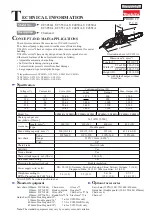
Fig. D-1
C
ircuit diagram
Field