


P 8/ 13
R
epair
[3] DISASSEMBLY/ASSEMBLY
[3] -3. Brake mechanism
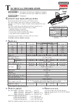
DISASSEMBLING
Fig. 10
1. Release brake by turning Front hand
guard complete to Front handle side.
4. Push Front hand guard forward so as
to activate the saw chain brake.
2. Remove Sprocket cover complete,
Retaining ring E type 6 and Flat washer 8
from the machine.
Sprocket cover
complete
3. Remove Brake drum
assembly (Sprocket)
from the machine.
(1) If Front hand guard is damaged, replace it with a new one as drawn in
Fig. 2
.
Note
: Be careful not to lose Compression spring 6.
(2) Disassemble Brake mechanism as drawn in
Fig. 10
.
Front hand guard
Front handle
Front hand guard
Retaining ring E
type 6
Flat washer 8
Brake drum
assembly
5. Remove two 5x25 Tapping screws and Spike bumper.
And then, remove two 5x25 Tapping screws and two 5x60
Tapping screws.
Spike bumper
(3) Remove Front handle, Tank cap complete, Gear housing cover, Oil tank with Connectors and Front hand guard.
(Refer to the
steps 4
to
9
in
Fig. 2
).
(4) Separate Motor housing from Gear housing. (Refer to the
steps 1
to
2
in
Fig. 3
).
5x25 Tapping screw (2 pcs.)
5x60 Tapping
screw (2 pcs.)
5x25 Tapping
screw (2 pcs.)


