


R
epair
[4] DISASSEMBLY/ASSEMBLY
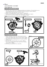
[4]-5. Recoil complete, Engine cover, Fuel tank (cont.)
P
7
/2
6
Fig. 17
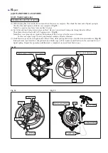
(3) Remove the fuel tubes of Tube assembly from Carburetor and Primer pump. (
Fig. 15
)
(4) Remove Fuel tank from Frame complete by unscrewing three M6x12 Pan head screws. (
Fig. 16
)
DISASSEMBLING
Fig. 15
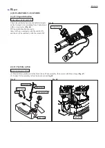
ASSEMBLING
Assemble by reversing the disassembly procedure.
Note:
•
When connecting the fuel tubes of Tube assembly to
Carburetor and Primer pimp, do not confuse them.
Be sure to connect the black one to Carburetor and
the transparent blue one to Primer pump. (
Fig. 15
)
•
When mounting Engine cover, be careful not to bend
nor pinch the breather pipe. (
Fig. 17
)
•
Do not forget to pass the fuel tubes of Tube assembly
through the slit of Engine cover. (
Fig. 18
)
Fig. 16
Black fuel tube
of Tube assembly
Transparent blue
fuel tube of
Tube assembly
Carburetor
Primer pump
Fuel tank
Breather pipe
M6x12 Pan head screw (3 pcs)
Tube assembly
Fig. 18
Engine cover,
viewed from the rear
slit of Engine cover


