


R
epair
[4] DISASSEMBLY/ASSEMBLY
[4]-3. Cock section
P
4
/2
6
Fig. 6
Fig. 7
Fig. 9
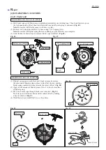
Cock body
(1) Remove Tube 10-500 and Tube 10-750 from Cock body by removing two 14 Hose clamps. (
Fig. 6
)
(2) Remove Body holder complete from Control lever assembly by unscrewing two 4x14 Tapping screws. (
Fig. 7
)
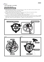
(3) Remove Body holder complete from Cock body
by unscrewing two 4x14 Tapping screws. (
Fig. 8
)
(4) Remove Push button from Cock body by unscrewing
Bind PT 3x16 Tapping screw. (
Fig. 9
)
(5) Remove Body cover from Cock body by unscrewing
two 4x14 Tapping screws.
Compression spring 12 can now be removed from
Cock body. (
Fig. 9
)
(6) Remove O ring 18 from Body cover. (
Fig. 9
)
(7) Remove Valve rod from Cock body, then remove
O ring 9 and O ring 12 from Valve rod. (
Fig. 9
)
Hose clamp 14
Tube 10-500
Tube 10-750
4x14 Tapping screw
(2 pcs)
Control lever assembly
Body holder complete
Fig. 8
4x14 Tapping screw
(2 pcs)
Cock body
Body holder complete
Cock body
Push button
Valve rod
Bind PT 3x16
Tapping screw
Compression
spring 12
Body cover
4x14 Tapping screw
(2 pcs)
O ring 12
O ring 9
O ring 18
DISASSEMBLING
ASSEMBLING
Assemble by reversing the disassembly procedure.
Note:
• Apply grease to the upper portion of O ring 12 on Valve rod.
• When mounting
Push button onto Cock body, fit the flat sides of Push button’s inside projection
in the flat sides of the hole of Valve rod.


