


R
epair
[4] DISASSEMBLY/ASSEMBLY
[4]-13. Stop switch section
[4]-14. Fuel tube section
P 2
1
/2
6
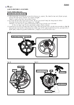
CHECKING STOP SWITCH
Check the continuity between the bullet terminals
on the two lead wires extending from Control lever
with a circuit tester. (
Fig. 66
)
If Stop switch functions properly,
there will be no continuity with the switch ON
and there will be continuity with the switch OFF.
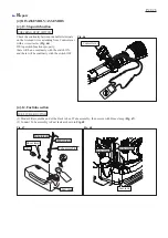
FUEL TUBE ROUTING
(1) Mount Filter onto the end of the black tube of Tube assembly, then secure with Hose clamp (
Fig. 67
)
(2) Connect Tube assembly to Fuel tank as shown in
Fig. 68
.
Fig. 67
Fig. 68
Fig. 66
Control lever
Tube (black)
Tube (blue)
Hose clamp
Filter
Tube assembly
Tube (black)
Tube (blue)
Fuel tank
Fuel tank


