


R
epair
[4] DISASSEMBLY/ASSEMBLY
[4]-15. Engine block
P 2
2
/2
6
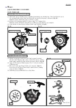
(1) It is highly recommended to drain the oil system of Engine block before starting disassembling
because the oil remaining there will drip out to delay your operation.
(2) From the engine section, remove the following parts (
Fig. 69
):
Ignition coil, Flywheel complete, Rocker cover complete, Rocker arm assembly (2 pcs), Push rod (2 pcs),
Cam lifter (2 pcs), Camgear assembly, Insulator complete, Air cleaner, Carburetor, Spark plug, Exhaust muffler
(3) Remove the assembly of Cylinder head and Cylinder block. (
Fig. 70
)
(4) Remove Ring spring 12 from each end of Piston pin with a pointed tool such as an awl as shown in the top of
Fig. 71
.
Note 1
: Be careful with Ring spring 12 because it can pop out unexpectedly during removal operation.
Note 2
: Do not use removed Ring spring 12. Be sure to replace it with
a
new one.
(5) Remove Piston pin with 1R286 or the like as shown in the bottom of
Fig. 71
.
(6) Remove Piston from Crankshaft complete.
Fig. 71
DISASSEMBLING ENGINE BLOCK
Piston pin
Ring spring 12
Piston
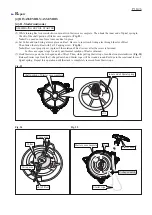
Fig. 70
Fig. 70
Crankcase
Piston
Crankshaft
complete
Cylinder head
Cylinder block
1R286
See "
[4]-10. Ignition system
"
for removal of
Spark plug, Ignition coil
and Flywheel complete.
See "
[4]-12. Carburetor section
"
for removal of
Carburetor and
Air cleaner.
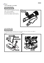
(1) Remove Tube 3-240 from Insulator complete.
(2) Remove Tube 3-25 from Cylinder block.
(3) Remove Insulator complete and Insulator gasket
by unscrewing two M5x25 Hex socket head bolts
and M5x14 Hex socket head bolt.
Removing Insulator complete:
Removing Muffler complete:
Remove Muffler complete and Muffler
gasket by unscrewing three M6x18 Hex
socket head bolts.
*Rocker arm assembly
consists of three parts
as shown below.
M5 Nut
Adjusting screw
Valve
(1) Remove Rocker cover complete and
Rocker cover gasket by unscrewing
two M5x30 Hex socket head bolts.
(2) Remove Camgear cover and
Cam gear gasket by unscrewing four
M5x16 Hex socket head bolts.
(3) Remove two Push rods.
(4) Remove Shaft and two Cam lifters
( 5973502300, 59735006KL).
(5) Remove Pin 5 and Camgear assembly.
(6) Remove two Rocker arm assemblies*
by removing Rocker arm shaft from
Cylinder head.
Removing Rocker arm and its relevant parts:


