


6
ENGLISH
Cordless grinder safety warnings
Safety warnings common for grinding, sanding,
wire brushing, or cutting-off operations:
1.
This power tool is intended to function as a
grinder, sander, wire brush, or cut-off tool.
Read all safety warnings, instructions, illus-
trations and specifications provided with this
power tool.
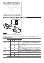
Failure to follow all instructions listed
below may result in electric shock, fire and/or
serious injury.
2.
Operations such as polishing or hole cutting
are not to be performed with this power tool.
Operations for which the power tool was not
designed may create a hazard and cause per
-
sonal injury.
3.
Do not convert this power tool to operate in
a way which is not specifically designed and
specified by the tool manufacturer.
Such a con-
version may result in a loss of control and cause
serious personal injury.
4.
Do not use accessories which are not spe-
cifically designed and specified by the tool
manufacturer.
Just because the accessory can
be attached to your power tool, it does not assure
safe operation.
5.
The rated speed of the accessory must be at
least equal to the maximum speed marked on
the power tool.
Accessories running faster than
their rated speed can break and fly apart.
6.
The outside diameter and the thickness of your
accessory must be within the capacity rating
of your power tool.
Incorrectly sized accessories
cannot be adequately guarded or controlled.
7.
The dimensions of the accessory mounting
must fit the dimensions of the mounting hard
-
ware of the power tool.
Accessories that do not
match the mounting hardware of the power tool
will run out of balance, vibrate excessively and
may cause loss of control.
8.
Do not use a damaged accessory. Before each
use inspect the accessory such as abrasive
wheels for chips and cracks, backing pad for
cracks, tear or excess wear, wire brush for
loose or cracked wires. If power tool or acces-
sory is dropped, inspect for damage or install
an undamaged accessory. After inspecting and
installing an accessory, position yourself and
bystanders away from the plane of the rotating
accessory and run the power tool at maximum
no-load speed for one minute.
Damaged acces-
sories will normally break apart during this test
time.
9.
Wear personal protective equipment.
Depending on application, use face shield,
safety goggles or safety glasses. As appro-
priate, wear dust mask, hearing protectors,
gloves and workshop apron capable of stop-
ping small abrasive or workpiece fragments.
The eye protection must be capable of stopping
flying debris generated by various applications.
The dust mask or respirator must be capable
of filtrating particles generated by the particular
application. Prolonged exposure to high intensity
noise may cause hearing loss.
10.
Keep bystanders a safe distance away from
work area. Anyone entering the work area
must wear personal protective equipment.
Fragments of workpiece or of a broken accessory
may fly away and cause injury beyond immediate
area of operation.
11.
Hold the power tool by insulated gripping
surfaces only, when performing an operation
where the cutting tool may contact hidden
wiring.
Contact with a "live" wire will also make
exposed metal parts of the power tool "live" and
could give the operator an electric shock.
12.
Never lay the power tool down until the acces-
sory has come to a complete stop.
The spinning
accessory may grab the surface and pull the
power tool out of your control.
13.
Do not run the power tool while carrying it at
your side.
Accidental contact with the spinning
accessory could snag your clothing, pulling the
accessory into your body.
14.
Regularly clean the power tool’s air vents.
The
motor’s fan will draw the dust inside the housing
and excessive accumulation of powdered metal
may cause electrical hazards.
15.
Do not operate the power tool near flammable
materials.
Sparks could ignite these materials.
16.
Do not use accessories that require liquid
coolants.
Using water or other liquid coolants
may result in electrocution or shock.
Kickback and related warnings:
Kickback is a sudden reaction to a pinched or snagged
rotating wheel, backing pad, brush or any other acces
-
sory. Pinching or snagging causes rapid stalling of the
rotating accessory which in turn causes the uncon
-
trolled power tool to be forced in the direction opposite
of the accessory’s rotation at the point of the binding.
For example, if an abrasive wheel is snagged or
pinched by the workpiece, the edge of the wheel that is
entering into the pinch point can dig into the surface of
the material causing the wheel to climb out or kick out.
The wheel may either jump toward or away from the
operator, depending on direction of the wheel’s move-
ment at the point of pinching. Abrasive wheels may also
break under these conditions.
Kickback is the result of power tool misuse and/or
incorrect operating procedures or conditions and can be
avoided by taking proper precautions as given below.
1.
Maintain a firm grip with both hands on the
power tool and position your body and arms
to allow you to resist kickback forces. Always
use auxiliary handle, if provided, for maximum
control over kickback or torque reaction during
start-up.
The operator can control torque reactions
or kickback forces, if proper precautions are taken.
2.
Never place your hand near the rotating acces-
sory.
Accessory may kickback over your hand.
3.
Do not position your body in the area where
power tool will move if kickback occurs.
Kickback will propel the tool in direction opposite
to the wheel’s movement at the point of snagging.
4.
Use special care when working corners, sharp
edges, etc. Avoid bouncing and snagging the
accessory.
Corners, sharp edges or bouncing
have a tendency to snag the rotating accessory
and cause loss of control or kickback.
Summary of Contents for GA041GZ02
Page 27: ...27...