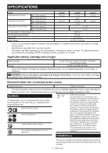
Makita GA041GZ02 Instruction Manual Download Page 4

4

ENGLISH

WARNING:


The vibration emission during actual use of the power tool can differ from the declared 

value(s) depending on the ways in which the tool is used especially what kind of workpiece is processed.

WARNING:


Be sure to identify safety measures to protect the operator that are based on an estimation 

of exposure in the actual conditions of use (taking account of all parts of the operating cycle such as the 

times when the tool is switched off and when it is running idle in addition to the trigger time).

WARNING:

 The declared vibration emission value is used for main applications of the power tool. However if 

the power tool is used for other applications, the vibration emission value may be different.

WARNING:


Grinding thin sheets of metal or other easily vibrating structures with a large surface can 

result in a total noise emission much higher (up to 15 dB) than the declared noise emission values. 

Set heavy flexible damping mats or such to those workpieces to prevent them from emitting sound.

Take the increased noise emission into consideration for both the risk assessment of noise exposure and 
selecting adequate hearing protection.

EC Declaration of Conformity

For European countries only

The EC declaration of conformity is included as Annex A 

to this instruction manual.

SAFETY WARNINGS

General power tool safety warnings

WARNING:


Read all safety warnings, instruc-

tions, illustrations and specifications provided 

with this power tool.

 Failure to follow all instructions 

listed below may result in electric shock, fire and/or 

serious injury.

Save all warnings and instruc-
tions for future reference.

The term "power tool" in the warnings refers to your 

mains-operated (corded) power tool or battery-operated 

(cordless) power tool.

Work area safety

1. 

Keep work area clean and well lit.

 Cluttered or 

dark areas invite accidents.

2. 

Do not operate power tools in explosive atmo-

spheres, such as in the presence of flammable 

liquids, gases or dust.

 Power tools create sparks 

which may ignite the dust or fumes.

3. 

Keep children and bystanders away while 
operating a power tool.

 Distractions can cause 

you to lose control.

Electrical safety

1. 

Power tool plugs must match the outlet. Never 
modify the plug in any way. Do not use any 
adapter plugs with earthed (grounded) power 
tools. 

Unmodified plugs and matching outlets will 

reduce risk of electric shock.

2. 

Avoid body contact with earthed or grounded 
surfaces, such as pipes, radiators, ranges and 
refrigerators.

 There is an increased risk of elec-

tric shock if your body is earthed or grounded.

3. 

Do not expose power tools to rain or wet con-
ditions.

 Water entering a power tool will increase 

the risk of electric shock.

4. 

Do not abuse the cord. Never use the cord for 
carrying, pulling or unplugging the power tool. 
Keep cord away from heat, oil, sharp edges 
or moving parts.

 Damaged or entangled cords 

increase the risk of electric shock.

5. 

When operating a power tool outdoors, use an 
extension cord suitable for outdoor use.

 Use of 

a cord suitable for outdoor use reduces the risk of 
electric shock.

6. 

If operating a power tool in a damp location 
is unavoidable, use a residual current device 
(RCD) protected supply.

 Use of an RCD reduces 

the risk of electric shock.

7. 

Power tools can produce electromagnetic 

fields (EMF) that are not harmful to the user.


However, users of pacemakers and other similar 
medical devices should contact the maker of their 
device and/or doctor for advice before operating 
this power tool.

Personal safety

1. 

Stay alert, watch what you are doing and use 
common sense when operating a power tool. 
Do not use a power tool while you are tired or 

under the influence of drugs, alcohol or med

-

ication.

 A moment of inattention while operating 

power tools may result in serious personal injury.

2. 

Use personal protective equipment. Always 
wear eye protection.

 Protective equipment such 

as a dust mask, non-skid safety shoes, hard hat or 

hearing protection used for appropriate conditions 

will reduce personal injuries.

3. 

Prevent unintentional starting. Ensure the 

switch is in the off-position before connecting 

to power source and/or battery pack, picking 
up or carrying the tool.

 Carrying power tools with 

your finger on the switch or energising power tools 

that have the switch on invites accidents.

4. 

Remove any adjusting key or wrench before 
turning the power tool on.

 A wrench or a key left 

attached to a rotating part of the power tool may 

result in personal injury.

5. 

Do not overreach. Keep proper footing and 
balance at all times.

 This enables better control 

of the power tool in unexpected situations.

6. 

Dress properly. Do not wear loose clothing or 
jewellery. Keep your hair and clothing away 
from moving parts.

 Loose clothes, jewellery or 

long hair can be caught in moving parts.

Summary of Contents for GA041GZ02

Page 1: ...INSTRUCTION MANUAL Cordless Angle Grinder GA039G GA040G GA041G ENGLISH Original instructions Read before use...

Page 2: ...table power pack PDC01 PDC1200 The cord connected power source s listed above may not be available depending on your region of residence Before using the cord connected power source read instruction a...

Page 3: ...tool is switched off and when it is running idle in addition to the trigger time Vibration The vibration total value tri axial vector sum determined according to EN62841 2 3 Work mode surface grindin...

Page 4: ...d power tools Unmodified plugs and matching outlets will reduce risk of electric shock 2 Avoid body contact with earthed or grounded surfaces such as pipes radiators ranges and refrigerators There is...

Page 5: ...s etc in accordance with these instructions tak ing into account the working conditions and the work to be performed Use of the power tool for operations different from those intended could result in...

Page 6: ...y from work area Anyone entering the work area must wear personal protective equipment Fragments of workpiece or of a broken accessory may fly away and cause injury beyond immediate area of operation...

Page 7: ...t off wheel from the cut while the wheel is in motion otherwise kickback may occur Investigate and take corrective action to eliminate the cause of wheel binding 4 Do not restart the cutting operation...

Page 8: ...oring battery cartridge in a con tainer with other metal objects such as nails coins etc 3 Do not expose battery cartridge to water or rain A battery short can cause a large current flow overheating p...

Page 9: ...10 The wireless unit is an accurate instrument Be careful not to drop or strike the wireless unit 11 Avoid touching the terminal of the wireless unit with bare hands or metallic materials 12 Always re...

Page 10: ...ausing injury to you or someone around you CAUTION Do not install the battery cartridge forcibly If the cartridge does not slide in easily it is not being inserted correctly Indicating the remaining b...

Page 11: ...ita Service Center Switch action CAUTION Before installing the battery car tridge into the tool always check to see that the slide switch actuates properly and returns to the OFF position when the rea...

Page 12: ...ture Soft start feature reduces starting reaction ASSEMBLY CAUTION Always be sure that the tool is switched off and the battery cartridge is removed before adjusting or checking function on the tool I...

Page 13: ...g to the work so that the oper ator can be protected Align the lock lever with one of the holes in the wheel guard and then release the lock lever to lock the wheel guard 2 1 A C C Fig 9 1 Wheel guard...

Page 14: ...ng wheel Not available in some countries Fig 12 Installing wire cup brush Optional accessory CAUTION Do not use wire cup brush that is damaged or which is out of balance Use of dam aged brush could in...

Page 15: ...not put your finger near the release lever while installing the X LOCK wheel It may pinch your finger NOTE No additional parts such as inner flanges or lock nuts are required to install or remove the...

Page 16: ...ing wheel guard and a vacuum cleaner Refer to the instruction manual attached to the dust collecting wheel guard for assembling and using it 1 2 Fig 20 1 Dust collecting wheel guard 2 Hose of the vac...

Page 17: ...depth of cut Overstressing the wheel increases the loading and susceptibility to twisting or binding of the wheel in the cut and the possibility of kickback wheel breakage and overheating of the motor...

Page 18: ...t optional accessory A vacuum cleaner which supports the wireless activation function The overview of the wireless activation function setting is as follows Refer to each section for detail procedures...

Page 19: ...If the hooks do not catch the wireless unit close the lid completely and open it slowly again Tool registration for the vacuum cleaner NOTE A Makita vacuum cleaner supporting the wireless activation...

Page 20: ...forming two or more tool registra tions for one vacuum cleaner finish the tool registra tion one by one Starting the wireless activation function NOTE Finish the tool registration for the vacuum clean...

Page 21: ...er to the table below for the meaning of the lamp status Status Wireless activation lamp Description Color On Blinking Duration Standby Blue 2 hours The wireless activation of the vacuum cleaner is av...

Page 22: ...d then become red After that press the wireless activation button on the tool in the same way 1 1 2 2 Fig 37 1 Wireless activation button 2 Wireless activation lamp If the cancellation is performed su...

Page 23: ...the power button on the vacuum cleaner is turned on Push the wireless activation button briefly and perform the tool registration cancellation procedures again The tool registration procedures for the...

Page 24: ...r formed by Makita Authorized Service Centers always using Makita replacement parts Air vent cleaning The tool and its air vents have to be kept clean Regularly clean the tool s air vents or whenever...

Page 25: ...thick ness greater than the maximum thickness as specified in SPECIFICATIONS the wires may catch on the guard leading to breaking of wires 2 6 7 4 5 5 2 2 8 10 9 3 1 Fig 40 Application 100 mm 4 model...

Page 26: ...to persons Only use accessory or attachment for its stated purpose If you need any assistance for more details regard ing these accessories ask your local Makita Service Center Makita genuine battery...

Page 27: ...27...

Page 28: ...www makita com Makita Europe N V Makita Corporation 3 11 8 Sumiyoshi cho Anjo Aichi 446 8502 Japan Jan Baptist Vinkstraat 2 3070 Kortenberg Belgium 885968 225 EN 20211221...

Reviews: