


13
ENGLISH
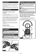
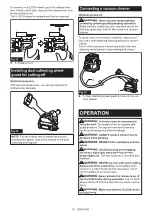
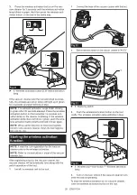
2.
While pushing the lock lever toward A, hold down
the portions B of the wheel guard as shown in the
figure.
2
B
1
A
B
Fig.8
►
1.
Wheel guard
2.
Hole
NOTE:
Push down the wheel guard straight.
Otherwise, you cannot secure the wheel guard.
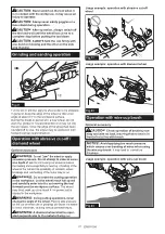
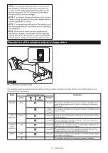
3.
While pushing the lock lever toward A, rotate the
wheel guard toward C, and then, change the angle of
the wheel guard according to the work so that the oper-
ator can be protected. Align the lock lever with one of
the holes in the wheel guard, and then release the lock
lever to lock the wheel guard.
2
1
A
C
C
Fig.9
►
1.
Wheel guard
2.
Hole
To remove wheel guard, follow the installation proce-
dure in reverse.
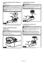
Installing depressed center wheel or
flap disc
Optional accessory
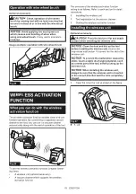
WARNING:
When using a depressed center
wheel or a flap disc, the wheel guard must be
fitted on the tool so that the closed side of the
guard always points toward the operator.
1
2
Fig.10
►
1.
Depressed center wheel
2.
Wheel guard
Summary of Contents for GA041GZ02
Page 27: ...27...