background image

PRODUCT

P  1/ 2

Straight unleaded gasoline

Yes

43.0 (2.6)

Models No.

 Description

C

ONCEPT AND MAIN APPLICATIONS

S

pecification

S

tandard equipment

O

ptional accessories

EM4350UH, EM4350LH

EM4351UH
Petrol Brushcutter

Primer pump

Engine

Displacement: cm³ (cu.in.)
Fuel

4-stroke

Specifications

EM4350LH

Model

Type

Loop handle

Handle style

Engine oil

Carburetor

SAE10W-30 oil

in the Class SF or higher of API Classification

(Automotive 4-stroke engine oil)

Diaphragm

These models are 43.0cm³ 4-stroke petrol brushcutters developed

in compliance with well-known exhaust emission regulations.

Their main features are:

• Powerful 4-stroke engine for working in larger open area, and

   for easily cutting through thick weeds and longer grass

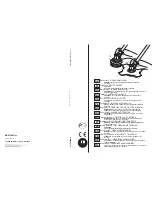
• Newly designed throttle assembly with wide-grip throttle trigger

• Universal guard for both metal blade and nylon cutting head

• Toolless quick fastening handle holder for easy handling and

   angle adjustment of handle


(for EM4350UH, EM4351UH only)

• Floating structure with four rubber buffers absorbs vibration

   transmitted from engine to bike handle. 

(for EM4351UH only)

Net weight

*

1

: kg (lbs)

7.9 (17.3)

*1 

Dry weight, without universal guard, cutting tool and shoulder harness

Note:

 The standard equipment for the tool shown above may vary by country.

Blade or Nylon cutting head ..................... 1

Universal guard (=Protector) .................... 1

Blade cover ............................................... 1 (for the model with blade)

Double shoulder straps with waist pad ..... 1 (for 

EM4350UH

)

Double shoulder straps with waist pad 

                         for Loop handle model...... 1 (for 

EM4350LH

)

Double shoulder straps with waist belt ..... 1 (for 

EM4351UH

)

Tool set (Hex wrench 4, Hex wrench 5,

                Socket wrench 16-17,

                Socket driver 16-10) .................. 1

Accessory bag ............................................ 1

Oil bottle without oil or 

Oil bottle containing 100mL engine oil ..... 1

255mm Triple blade,  300mmTriple blade, 255mm Star blade,  200mm Chisel blade, 225mm Chisel blade,  

Nylon cutting heads (UltraAuto 6), Protector, Protector extension, Protector 200 set, Protector 225 set, 

Double shoulder straps, Oil bottle
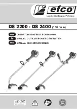
635 (25)

339 (13-3/8) 618 (24-1/4)

Dimensions: mm (")

Width (W)
Height (H)

Length (L)

1,812 (71-1/2)

The drawing 

above is 

EM4350UH.

1,812 (71-1/2)

460 (18-1/8)

528 (20-3/4)

250 (9-7/8)

EM4350UH EM4350LH EM4351UH

Anti-vibration system

EM4351UH

EM4350UH

Bike handle

8.3 (18.2)

Conventional low-vibration structure

Yes

1.50 (2.1) at 7,500 rpm

Engine start assist

Yes

(by automatic mechanical decompression valve) 

7,200

Bike handle

Floating structure

8.6 (18.9)

Clutch

0.62 (21.0)

Fuel tank capacity: L (US oz)

M10x1.25, Left-handed

Spindle thread size

L

EM4350UH

EM4351UH

H

W

EM4350LH

L

W

H

Max. spindle speed at no load: min.

ˉ

¹ = rpm

Max. torque: N.m

Max. output: kW (PS)

2.1 at 5,500 rpm

T

ECHNICAL INFORMATION

Summary of Contents for EM4350UH

Page 1: ...andard equipment for the tool shown above may vary by country Blade or Nylon cutting head 1 Universal guard Protector 1 Blade cover 1 for the model with blade Double shoulder straps with waist pad 1 for EM4350UH Double shoulder straps with waist pad for Loop handle model 1 for EM4350LH Double shoulder straps with waist belt 1 for EM4351UH Tool set Hex wrench 4 Hex wrench 5 Socket wrench 16 17 Sock...

Page 2: ... starter and the spline ends of Shaft in Shaft pipe complete 2 When the inside of Gear case is cleaned supply 11g of Makita grease N No 2 from the grease inlet 3 Apply 4g of Makita grease N No 1 to the entire portion of Shaft in Shaft pipe complete 4 Once Engine is disassembled remove oil grease from the mating surface of Cylinder and Crankcase complete then apply ThreeBond 1215 1216 to the mating...

Page 3: ... holes of Pipe housing Fig 4 For EM4350UH and EM4350LH Remove M5x8 Hex socket head bolt and M6x30 Hex socket head bolt from the threaded holes of Clutch case Fig 5 6 Grab Shaft pipe complete by hand then pull it off from Clutch case If Shaft sticks in Clutch case use water pump pliers or the like to pull it off Note Be sure to wrap Shaft with a rag or the like to protect it from water pump pliers ...

Page 4: ...r extension attached Fig 8 2 Enlarge the space between the side wall of Protector cover and M5x14 Hex socket head bolt and remove Protector cover from Shaft pipe complete Fig 9 3 Remove two M5x14 Hex socket head bolts then remove Protector clamp 4 Loosen M6x30 Hex socket head bolt then remove Gear case assembly Fig 10 Fig 7 Play 3mm to 4mm Cable bracket of Insulator complete Stopper on Inner cable...

Page 5: ...move four M5x30 Hex socket head screws then remove Handle clamp 28 and then remove Loop handle 28 Fig 14 6C Loosen two M5x14 Hex socket head bolts then separate Lever case set from Pipe shaft complete Fig 15 7C Remove the following parts from Pipe shaft complete Hanger set Spacer Shaft Fig 11 Fig 13 Fig 14 Fig 15 Fig 12 DISASSEMBLING M5x30 Hex socket head screw 4 pcs Handle clamp 28 Shaft Shaft pi...

Page 6: ... Housing holder into the other Buffer rubbers then tighten M5x18 Hex socket head bolt while holding Housing holder by hand Fig 17 Note Make sure that Corrugate tube is put in the groove of Pipe housing Fig 18 3A Assemble by reversing the disassembly procedure For 4350UH and 4350LH Assemble by reversing the disassembly procedure Fig 16 Fig 18 Fig 17 ASSEMBLING Ribs of Pipe housing Projections of Cl...

Page 7: ... 8 Preset Receive washer and 1R033 with M10 17 Hex nut to Cutter shaft complete as drawn in Fig 25 and give the impacts using the plastic hammer An assembled part of Cutter shaft complete and Ball bearing 6201LLU is removed Refer to Fig 26 for the components 9 Remove Ball bearing 6201LLU with 1R045 Neither Spiral bevel gear 13 or Cutter shaft set is supplied individually It is supplied as a set Cu...

Page 8: ...terclockwise Fig 28 2 Remove Clutch base by turning the hex portion counterclockwise Fig 29 1 Set Clutch base in place by turning the hex portion clockwise 2 Set two Clutch shoes and Tension springs 5 in place by tightening each M8 Shoulder hex bolt clockwise first by hand then with a cordless impact driver This is because the M8 Shoulder hex bolt is a shoulder bolt Therefore tighten by hand until...

Page 9: ... ring R 35 in Clutch case with 1R006 Fig 37 3B Put 1R247 on Clutch drum in Clutch case press down Clutch drum using Arbor press Fig 38 Note If it is difficult to remove Clutch drum from Clutch case warm Clutch case with a heat gun 4B Remove Retaining ring S 17 from Clutch drum with 1R004 5B Remove Ball bearing 6003LLU from Clutch drum with 1R045 Fig 35 Fig 34 Fig 32 Fig 33 DISASSEMBLING Clutch cas...

Page 10: ...0LH and 4350UH 1 Press fit Ball bearing 6003LLU to Clutch drum with 1R031 in Fig 42 Note Put Retaining ring R 35 between Ball bearing 6003LLU and Clutch drum in advance 2 Set Retaining ring S 17 in the groove on Clutch drum 3 Put Clutch case on the table of Arbor press horizontally without tilt and press fit Spacer and Clutch drum into Clutch case with 1R286 Fig 43 4 Set Retaining ring R 35 to the...

Page 11: ...ed socket wrench Note If the electrodes of Spark plug are wet wipe them with a rag then dry them with an air blower 2 Using a wire brush carefully clean up carbon deposits if any from the electrodes and the ceramic insulator around the center electrode 3 Adjust the electrode gap to 0 7 to 0 8mm by carefully bending the side electrode Use Feeler gauge set 1R366 to check the gap width between the ce...

Page 12: ...9 Fig 50 Fig 51 DISASSEMBLING ASSEMBLING M8 Collared Hex nut 1 Turn M8 Collared Hex nut in the center of Flywheel counterclockwise using a cordless impact driver Fig 49 2 Mount 1R364 on Flywheel then screw two M5 bolts of 1R364 into Flywheel as drawn in Fig 50 Flywheel can now be removed from Crankshaft complete by turning the center bolt of 1R364 clockwise using a screwdriver or the like Importan...

Page 13: ...w Starter rope through Starter cover Then tie one end to Starter knob and the other to Reel by making a knot Fig 55 4 Make sure that the inner end of Spiral spring is positioned close to the shaft portion of Starter cover for the step 6 Then put Reel in Starter cover 5 Wind Starter rope around Reel two or three times 6 While turning Reel counterclockwise mount it in Starter cover The inner end of ...

Page 14: ... assembly in place make sure that the tip of Inlet needle is neither worn nor deformed Fig 62 Note The inner parts are not available individually If you need any of the inner parts order Pump body assembly 5 When mounting Control lever make sure that the upper end of Spring is firmly held in place under the projection of Control lever Fig 63 6 Remove the pan head screw of Pump cover Fig 64 7 Make ...

Page 15: ...nect three Tubes to Carburetor as drawn in Fig 68 Then connect Tube 5 160 and Pipe to Cleaner plate assembly as drawn in Fig 69 3 Mount Air cleaner element onto Cleaner plate assembly 4 Mount Air cleaner cover complete onto Air cleaner plate then secure with M5x20 Hex socket head bolt Fig 1 of 4 2 Note Be sure to fit the tab of Cleaner plate assembly into the slot of Cleaner cover assembly Fig 66 ...

Page 16: ...ube 3 120 to the short pipe of Primer pump Also refer to Fig 68 3 Put Coil spring 8 and Clamp on Tube 3 150 Fig 67 4 Route Tube 3 150 as drawn in Fig 68 Route Tube 3 120 between Tube 3 150 and Cleaner plate assembly Fig 69 Tube 3 260 black Holders of Cleaner plate assembly Fuel tank Breather to intake air into Tank Tube 3 150 blue to intake air into Tank 4 12 Fuel tube section Tube complete Breath...

Page 17: ...e the assembly of Cylinder head and Cylinder block Fig 70 4 Remove Clip 2 pcs in total from each end of Piston pin with a pointed tool such as an awl as shown in Fig 71 Note Be careful with Clip because it can pop out unexpectedly during removal operation Do not use removed Clip Be sure to replace it with new one 5 Remove Piston pin with 1R171 or the like as shown in Fig 72 6 Remove Piston from Cr...

Page 18: ...shown in Fig 75 If both of the two rings are used and the T marking of Second ring is rubbed off carefully press the side face of the two rings to the inner wall surface of Cylinder You will be able to distinguish the two rings or to discriminate the large diameter of Second ring through the differences in contact feelings that the different side faces make Fig 73 Top ring Second ring Fig 74 Fig 7...

Page 19: ...f of 1R366 into the clearance between Rocker arm and Valve section Re Fig 81 then adjust the valve clearance 6 After checking the feeler gauge can be passed through the clearance and the clearance itself is not more than 0 12mm tighten Hex nuts of Rocker arm assembly securely and then remove the gauge from the clearance Note While making two Rocker arms close to the center Fig 82 adjust the valve ...

Page 20: ...e so as not to fall off Intake valve and Exhaust valve The rag works as protection of the inside of Cylinder block assembly 3 Remove Cotters Retainers and Compression springs 11 from Intake valve and Exhaust valve with 1R389 and 1R005 Figs 86 and 87 Fig 85 Fig 86 Fig 87 ASSEMBLING DISASSEMBLING 4 14 Valve section Rocker arm assembly 2 pcs Pin 5 1R005 Cotter 4 pcs Cotter 4 pcs Retainer 2 pcs Compre...

Page 21: ...ression spring 11 to Cylinder block assembly as drawn in Figs 87 and 86 then while pushing Compression springs 11 pass the valve tops through the holes of Retainers Figs 90 and 91 Then assemble Retainers cotters and valves each other Note If it is difficult to assemble them use 1R389 with 1R005 4 Set Pin 5 and two Rocker arm assemblies in place of Cylinder block assembly Fig 85 10mm up to 15mm 10m...

Page 22: ...cs Cylinder block Engine base Spark plug Spark plug M10 pitch 1 0 Insulator complete Cylinder block M5x20 Hex socket head bolt 2 pcs 6 0 6 0 16 0 11 0 11 0 12 0 6 0 Starter cover assembly M5x20 Hex socket head bolt 4 pcs 5 0 Muffler plate M5x18 Hex socket head bolt 3 pcs 5 0 5 0 Oil pipe Oil case M5x18 Hex socket head bolt 4 0 Cleaner plate assembly Insulator M5x60 Hex socket head bolt Crank case ...

Reviews: