background image


6

/ 1

2

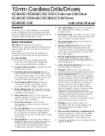
When handling or storing multiple Rotors, be sure to keep a proper distance between Rotors as shown in 

Fig. 9A

because Rotor is a strong magnet, failure to follow this instruction could result in:


 Finger injury caused by pinching between Rotors pulling each other


 Magnetic loss of Rotors or damage on the magnet portion of Rotor. (

Fig. 9B

)     


Fig. 9A

Fig. 9B

* Magnetic loss of Rotors

* Damage on the magnet portion of Rotor 

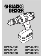
1. Put Leaf spring in place as drawn below. 

(1) Pass Rotor into Stator complete as drawn in 

Fig. 10

.

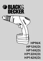
(2) Mount Leaf spring to Housing L, and join Gear assembly with Motor section. (

Fig. 11

)

Caution for Handling of Rotor

ASSEMBLING

Leaf  spring

Fig. 10

Fig. 11

1. Holding Stator complete on a workbench, slowly insert Rotor 

    in Stator complete until Rotor’s drive end reaches the workbench. 

2. When the drive end of Rotor 

    reaches the workbench, lift up

    Stator complete slowly.

Rotor

Stator complete

Gear 

assembly

2. Before pushing Rotor section (Rotor and Stator) fully

    in Gear assembly, make sure that Rotor’s gear engages

    with the super gears of Gear assembly to rotate them 

    smoothly.

Motor section

R

epair

[3] DISASSEMBLY/ASSEMBLY

[3] -2. Rotor, Gear assembly (cont.)

Summary of Contents for DHP480

Page 1: ...h W Height H Length L 199 7 7 8 79 3 1 8 243 9 9 16 1 260 10 1 4 2 Battery Capacity of drill chuck mm Capacity mm Max lock torque N m in lbs Electric brake Variable speed control Mechanical speed cont...

Page 2: ...rench with strong fastening torque such as Model BTW450 440 N m in max fastening torque Remove Drill chuck as drawn in Fig 2 1 Remove M6x22 Flat head screw Then preset the machine as drawn in Figs 1 2...

Page 3: ...of Hex wrench 10 Hex wrench 10 viewed from side A Clamp flat surfaces of Hex wrench 10 A Hex wrench 10 viewed from side A Hex wrench 10 Hex wrench 10 Vise 2 Setting the machine as illustrated below p...

Page 4: ...assemble Gear assembly until Spindle can be seen Fig 6A 2 Assemble Lock cam to Carrier C complete then attach them to 1R359 Fig 6B 3 Fix 1R359 securely in vise 4 Insert the spline portion of Spindle i...

Page 5: ...L Housing R 3x16 Tapping screw 9 pcs Change ring Stator Rotor Gear assembly Speed change lever Housing L Housing L Repair 3 DISASSEMBLY ASSEMBLY 3 2 Rotor Gear assembly 3 Remove Speed change lever fr...

Page 6: ...o Stator complete as drawn in Fig 10 2 Mount Leaf spring to Housing L and join Gear assembly with Motor section Fig 11 Caution for Handling of Rotor ASSEMBLING Leaf spring Fig 10 Fig 11 1 Holding Stat...

Page 7: ...it stops to have space between the pin of Gear assembly and the rear Compression spring 4 3 Fit the pin of Gear assembly to Spring s coil with slowly returning Speed change lever assembly toward Drill...

Page 8: ...e sure that the ribs of Housing L are fitted tightly in the notches of Stator F R Change lever 2 Before assembling Switch to Housing L fit the prong of F R change lever to the projection of Switch pro...

Page 9: ...g D 2 White Red Orange Yellow LED Connector Controller Terminal Stator Printed wiring board Blue B2 B1 T T AS Switch Terminal Connector Housing L Wiring to Switch Housing L Flag terminal Flag connecto...

Page 10: ...n of Lead wires of Printed wiring board to the space keeping the distance from the tip of Rib A toward LED side Put the slack portion of Lead wires of Stator and those of Controller for connecting to...

Page 11: ...broken Replace Controller Connect it firmly Check Lead wires or replace it LED indicator lamps are on Switch is broken Yes Yes Yes Yes Yes No No No No No Controller is broken Rotor is broken Stator i...

Page 12: ...ch Tester bar red to Pole of Terminal to which Lead wire black is connected 2 Attach Tester bar red to any of UVW terminals of Stator unit orange white or blue lead wires 2 Attach Tester bar red to an...

Reviews: