background image

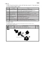
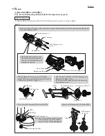
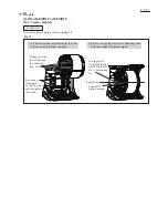
2. Lock Switch lever complete 

    with an insulating tape or a like.

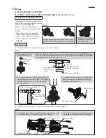
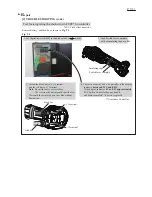
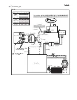
[4] TROUBLE SHOOTING (cont.)

Test for recognizing the short-circuit of FET* on controller

Fig.  T-3

Remove Battery, and then do as shown in 

Fig. T-3

.

3. Attach the black bar to (+) Terminal,

    and the red bar to (-) Terminal.

    Note

: Be careful not to reverse them.

              The reverse attachment could spoil the test. 

    Wait until the display shows the value without 

    fluctuation. 

(+) Terminal

(-) Terminal

Insulating tape
Switch lever complete

black bar

red bar

P 9/ 11

1. Set Digital tester (1R402) in the diode mode (           mark).

*FET: Field effect transistor 

R

epair

**It includes Controller.

4. There is no fault of FET on Controller if the display

     indicates

 between 0.79V and 0.81V

     If the display indicates 

0V or 0.4V approximately

     FET built in Controller has any trouble, 

     and Stator complete** has to be replaced. 

Summary of Contents for DGA405

Page 1: ...ergy capacity Wh 27 36 54 72 90 Charging time approx min 15 24 22 36 45 with DC18RC Wheel size mm Hole diameter 6 1 4 Max thickness Diameter 100 4 16 5 8 22 23 7 8 8 500 No Yes Yes Yes Yes Yes Paddle...

Page 2: ...bevel gear 37 to Spindle supporting Spindle when assembling Spiral bevel gear 37 to Spindle disassembling Rotor from Gear housing cover supporting Bearing box when removing Spindle from Spiral bevel...

Page 3: ...d hand turn M6 Hex nut counterclockwise with Wrench 10 Then remove Spiral bevel gear 10 4 Hook the jaws of 1R045 with Gear housing cover then push out Rotor ass y In this step Ball bearing 629LLB stil...

Page 4: ...cure the gear by turning M6 Hex nut clockwise with Wrench 10 Keep enough distance between Rotors so that they are out of their magnetic forces each other ASSEMBLING Spiral bevel gear 10 M6 Hex nut Fig...

Page 5: ...Spindle and Spiral bevel gear 37 are removed 4 Remove Retaining ring R 32 with 1R291 from the groove in Bearing box 5 Turn Bearing box upside down and press down Ball bearing 6201DDW from Bearing box...

Page 6: ...gear 37 Bearing box 1R029 1R036 Ball bearing 696ZZ Ring spring 11 3 Apply 1R268 to Shoulder pin 4 through the small hole on Pin cap and tap 1R268 with Metal hammer Shoulder pin 4 is removed from Gear...

Page 7: ...tor complete Assemble Stator complete as drawn in Fig 13 3 DISASSEMBLY ASSEMBLY 3 4 Stator complete ASSEMBLING Mating cavity on the left side and the right side tow each Terminal of Stator complete Ce...

Page 8: ...ace the broken wire s Lead wires are broken Check Lead wires or replace the broken wire s Rotor ass y is broken Stator complete is broken Switch is broken Replace Switch Terminal is broken a Mode lamp...

Page 9: ...everse attachment could spoil the test Wait until the display shows the value without fluctuation Terminal Terminal Insulating tape Switch lever complete black bar red bar P 9 11 1 Set Digital tester...

Page 10: ...and fasten the plate with the M3 5 screw of Switch Switch unit Tape Terminal Connector AWG24 AWG24 AWG28 AWG14 AWG28 AWG22 AWG14 AWG14 AWG14 Controller Line filter if used Stator P 10 11 Circuit diagr...

Page 11: ...Switch Route lead wires red yellow black of Terminal between Rib E and Rib F Put Line filter between Rib G and Rib H P 11 11 Wiring diagram Bend thick lead wires orange white blue of Controller here s...

Reviews: