
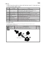


Notch
Switch lever complete
[3] DISASSEMBLY/ASSEMBLY
[3]-1. Rotor, Ball bearing 629LLB, 607LLB, Spiral bevel
gear 10 (cont.)
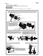
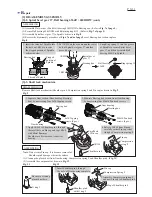
Fig. 3R
Fig. 3F
Caution for Handling of Rotor
When handling or storing multiple Rotors,
be sure to keep a proper distance between
Rotors as shown in
Fig. 3R
Because Rotor is a strong magnet,
failure to follow this instruction could
result in:
• Finger injury caused by pinching
between Rotors pulling each other.
• Magnetic loss of Rotors or damage
on the magnet portion of Rotor.
(
Fig. 3F
)
* Magnetic loss of Rotors
* Damage on the magnet
portion of Rotor
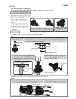
Ball bearing
607LLB
Rotor
1. Assemble Ball bearing
607LLB to Rotor.
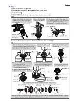
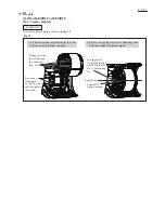
(1) Assemble Rotor ass’y to Gear housing cover as drawn in
Fig. 4.
(2) Assemble Gear housing cover and Gear housing section as drawn in
Fig. 5.
4. Assemble Spiral bevel gear 10 to Rotor ass’y,
and secure the gear by turning M6 Hex nut
clockwise with Wrench 10.
Keep enough distance between Rotors so that
they are out of their magnetic forces each other.
ASSEMBLING
Spiral bevel gear 10
M6 Hex nut
Fig. 4
Fig. 5
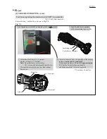
Gear housing
Spindle
Gear housing cover
2. Assemble Gear housing to Gear housing cover.
Face Spindle toward Switch lever complete.
1. Assemble Gear housing cover to Motor housing. Face the notch
of Gear housing cover toward Switch lever complete.
P 4/ 11
2. Assemble O ring 26 to the inner groove of Gear housing cover, and apply Makita grease
R No. 00 to the inner periphery of O ring 26, and then, insert Ball bearing 629LLB from
the large hole side of Gear housing cover.
3. Receive the inner race of Ball bearing 629LLB
in Gear housing cover with 1R027, and pressfit
the shaft of Rotor ass’y into the hole of Ball
bearing 629LLB.
Large hole of
Gear housing
cover
O ring 26
with Grease R No. 00
on the inner periphery
Ball bearing 629LLB
1R027
Hole of Ball bearing 629LLB
Inner race of Ball
bearing 629LLB
R
epair


