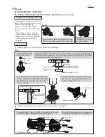
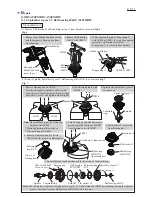

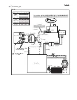


Fig. D-2
Wiring of Controller to Stator complete
Wiring after setting Switch and Switch unit
Pin A
Pin B
Boss for fitting
Switch unit
Boss A
Rib B
Rib A
Rib D
Boss B
Rib F
Rib E Connectors
Stator
Rib G
Controller
Terminal
Line filter (if used)
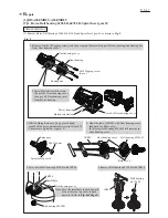
Rib H
Housing set R side
Housing set R side
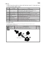
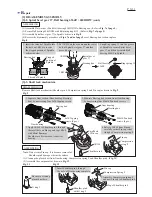
Note
: Insert the plate end of Non-insulated terminal into Switch terminal No. 3
as drawn in
Figs. R
and D-1 of page 10.
Switch unit
Fig. R
Fig. F
Housing
set L
Housing
set L
Switch
Switch
Switch
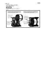
Route lead wires (red, yellow, black) of Terminal
between Rib E and Rib F.
Put Line filter between Rib G and Rib H.
P 11/ 11
W
iring diagram
Bend thick lead wires (orange, white, blue) of Controller
here so as not to pinched between mating portions of
Housing L and R.
Fix Lead wires in these Lead wire holders one by one.
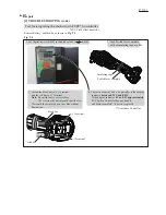
Route three thick lead wires (orange, white, blue)
of Controller between Pin A and Pin B.
Route Polyolefin tube of Controller between;
• Rib A and Boss A
• Rib B and Boss for Switch unit fitting
• Rib B and Rib D
• Pin A and Boss B
Put Connectors (of Lead wires
for Switch unit and Controller)
in this space.
Fix Lead wires from Switch unit
in these Lead wire holders.