P 6 / 8
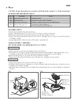
[3] DISASSEMBLY / ASSEMBLY
[3]-6. Disassembling/ Assembling Motor Section (cont.)
R
epair
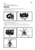
1) When mounting Yoke on Motor housing R, fit the notch of Yoke into
the protrusion of Motor housing R. (
Fig. 14
)
2) Insert Armature gear shaft to gear room of Handle R, and fix Motor housing to
Handle R by tightening 4x30 Tapping screws (4 pcs.).
Note
: Magnetic force pulls Motor housing with Yoke and Armature. Therefore,
Do not pinch finger and Lead wires (
Fig. 14
) in this step.
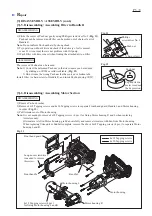
3) Set Ring 30, Switch lever and Lock-off button in place, then Match Handle L
with Handle R and tighten Tapping screws. (
Fig. 13
)
Note
: Magnetic force pulls Motor housing with Yoke and Armature. Therefore,
Do not pinch Lead wires (
Fig. 15
) in this step.
ASSEMBLING
Notch of Yoke
Protrusion of
Motor housing R
Fig. 14
Fig. 15
Lock-off button
Switch lever
Ring 30
Do not pinch finger and Lead wires between
Motor housing and Handle.
Do not pinch finger and Lead
wires in this area.


