background image

R

epair

It is not required to lubricate the gear section because the portion is replaced as a factory- lubricated gear unit.

[3] DISASSEMBLY/ASSEMBLY

[3] -1. Drill Chuck

[1] NECESSARY REPAIRING TOOLS

CAUTION: Repair the machine in accordance with “Instruction  manual” or “Safety instructions”.

Code No.

Description

Use for

1R359 Drill chuck removing tool

[2] LUBRICATION

DISASSEMBLING

Hex wrench 10

(Use this tool if Drill chuck cannot be removed by the method of

  described in “[3]-1 Drill chuck disassembling”.)

removing/ mounting Drill chuck
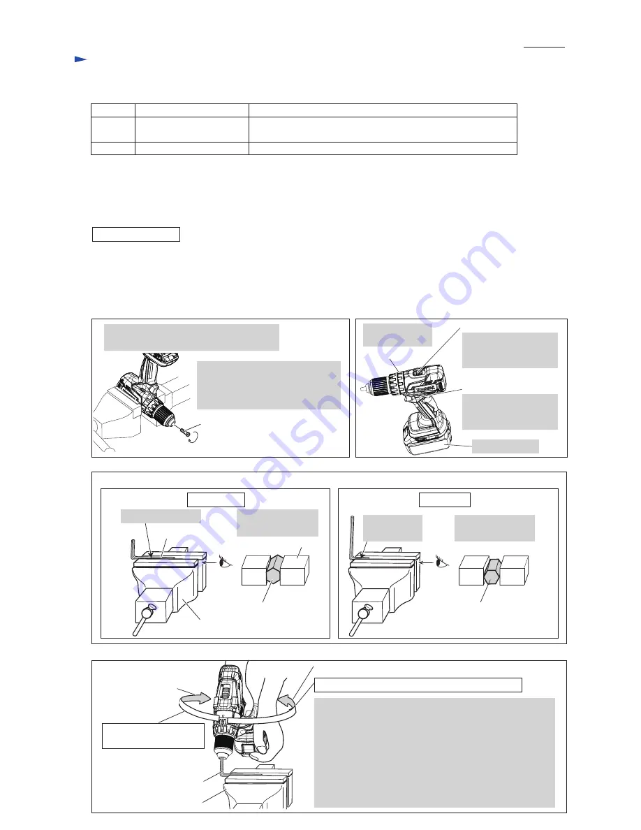
Fig. 1

M6x22 Flat head screw

(Left handed thread)

Note

: It is required to remove Drill chuck when replacing Gear assembly, but you need not when replacing

          the parts that are independent of Gear assembly.

(1) Remove M6x22 Flat head screw. (

Fig. 1

)

(2) Preset the machine. (

Fig. 2

)    And set Hex wrench 10 to Vise. (

Fig. 3

)

(3) While holding Hex wrench 10 with Drill chuck firmly, remove Drill chuck from Gear assembly. (

Fig. 4

)

Fig. 2

Attach Battery. 

F/R change lever 

Set F/R Change lever

to 

Reverse

 (

counter-

clockwise

) rotation.  

Set Speed change lever

to Low speed mode

designated with 1. 

Speed change lever

Set Change ring

to Drill mode.  

Change ring

Open Drill chuck fully and remove M6x22

Flat head screw by turning it 

clockwise

CORRECT

WRONG

Fig. 3

Fig. 4

Setting of Hex wrench10 

Vise

Grip flat surfaces

of Hex wrench 10.

Hex wrench 10

Hex wrench 10,

viewed from side [A]

Vise

Hold the long end.

[A]

Do not hold edges

of Hex wrench 10.

Do not hold

the short end.

Hex wrench 10,

viewed from side [A]

Note

: Use Impact driver to unscrew

           M6x22 Flat head screw if it

           could not be removed

           manually. 

[A]

Clockwise

Counterclockwise

Hex wrench 10

Vise

Clockwise

*

1

 recoil force

of Machine   

Note: 

The rotational direction is viewed from operator.

1. Hold Hex wrench 10 with Drill chuck and grip Machine.

    Important

:

    Grip Machine tightly with both hands to provide

    the sufficient counterclockwise

*

2

 force against

    clockwise

*

1

 recoil force of Machine.

2. Pull Switch trigger slowly.

3. Spindle rotates counterclockwise

*

2

 and consequently

Drill chuck is removed from spindle.

Counterclockwise

*

2

 force to be applied by operator


P  

3

/ 1

1

Summary of Contents for BHP459

Page 1: ...torque N m in lbs Torque setting Steel Wood Soft joint Hard joint No load speed min 1 rpm Energy capacity Wh Voltage V Capacity Ah High Weight according to EPTA Procedure 01 2003 kg lbs Low Max outpu...

Page 2: ...No DC18RC Charger No Yes BL1830 BHP459RFE3 BHP459RH BHP459RHE BL1815 Yes Yes 2 1 DC18RC BHP459SHE 2 1 DC18SD BL1815 BHP459 Housing color BHP459RFEW 2 1 Makita blue Makita blue Makita blue White Note...

Page 3: ...R change lever Set F R Change lever to Reverse counter clockwise rotation Set Speed change lever to Low speed mode designated with 1 Speed change lever Set Change ring to Drill mode Change ring Open D...

Page 4: ...to vise Refer to Fig 3 4 Tighten Drill chuck Fig 7 M6x22 Flat head screw Left handed thread Turn Drill chuck clockwise by hand until it is seated on the end of the threaded portion of Spindle Note App...

Page 5: ...nd rear Compression spring 4 5 While lifting up Rotor side of Speed change lever assembly pull it toward the direction designated with black arrow Pin on the lever of Gear assembly front Compression s...

Page 6: ...d change lever assembly Fig 12 rear Compression spring 4 The front Compression spring 4 compressed by the lever of Gear assembly Drill chuck side Rotor side Pin on the lever of Gear assembly Drill chu...

Page 7: ...groove 1 Make sure to put Leaf spring in place as drawn below Assemble Gear assembly and Rotor section to Housing L Fig 13 Fig 14 F R Change lever can be assembled to Switch Fig 14 Stator Rib Rib Bef...

Page 8: ...P 8 11 Circuit diagram Fig D 1 Color index of lead wires sheath Black White Red Orange Blue LED Light Yellow Controller Stator Printed wiring board Switch Terminal Terminal Connector B1 B2 Connector...

Page 9: ...e tightened between LED bushing and Lead wire holder when routing these wires between the following Ribs and Boss the space between Ribs A and C the space between Ribs A and B the space between Ribs A...

Page 10: ...terminals Be careful not to put Lead wires on this Boss Put the slack portion of Lead wires of Stator and those of Printed wiring board in this place Put one or more Lead wires of Stator into both Lea...

Page 11: ...e faced to the opposite side of Lead wires of Stator Stator Printed wiring board Printed wiring board By fastening four screws assemble Printed wiring board to Insulator without wobbling Note The scre...

Reviews: