background image

C

ONCEPT AND MAIN APPLICATIONS

Model HP332D is a Cordless hammer driver drill powered by 10.8V (12V max

*

4

)

slide Li-ion battery.

• More compact and more work amount compared with the current model

  HP330D thanks to the newly developed brushless motor and newly

  developed 10.8V (12V max

*

4

) slide Li-ion battery

• Best possible ergonomic handle for drilling/driving applications

S

Model

HP332D

Battery

Voltage: V

10.8

Capacity: Ah

1.5, 2.0, 4.0

Energy capacity: Wh

17, 22, 44

Cell

Li-ion

Type

Slide

Charging time (approx): min

50, 70, 130 with DC10WC

*

3

; DC10WD

*

4

22, 30, 60 with DC10SA

*

3

; DC10SB

*

4

Max output power (W)

250

No load speed: min

-1

= rpm

2nd (High)

0-1,500

1st (Low)

0-450

Impacts per minute:

min

-1

= ipm

2nd (High)

0-22,500

1st (Low)

0-6,750

Capacity of drill chuck: mm (")

0.8 (1/32) - 10 (3/8)

Capacity: mm (")

Masonry

8 (5/16)

Steel

10 (3/8)

Wood

28 (1-1/8)

Torque setting

20 drill mode

Clutch torque setting: N·m (in·lbs)

1.0 (9) - 5.0 (44)

Max tightening

torque: N·m (in·lbs)

Hard joint

35 (310)

Soft joint

21 (190)

Max lock torque: N·m (in·lbs)

32 (280)

Electric brake

Yes

Mechanical speed control

Yes (2-speed)

Variable speed control

Yes (by trigger)

Reversing switch

Yes

LED job light

Yes

Weight according to

EPTA-Procedure 01/ ver.2.1: kg (lbs)

1.1 (2.4)

*

or 1.3 (2.8)

*

2

*3

For all countries except North, Central and South American countries, Asia, Australia

*4

For North, Central and South American countries, Asia, Australia

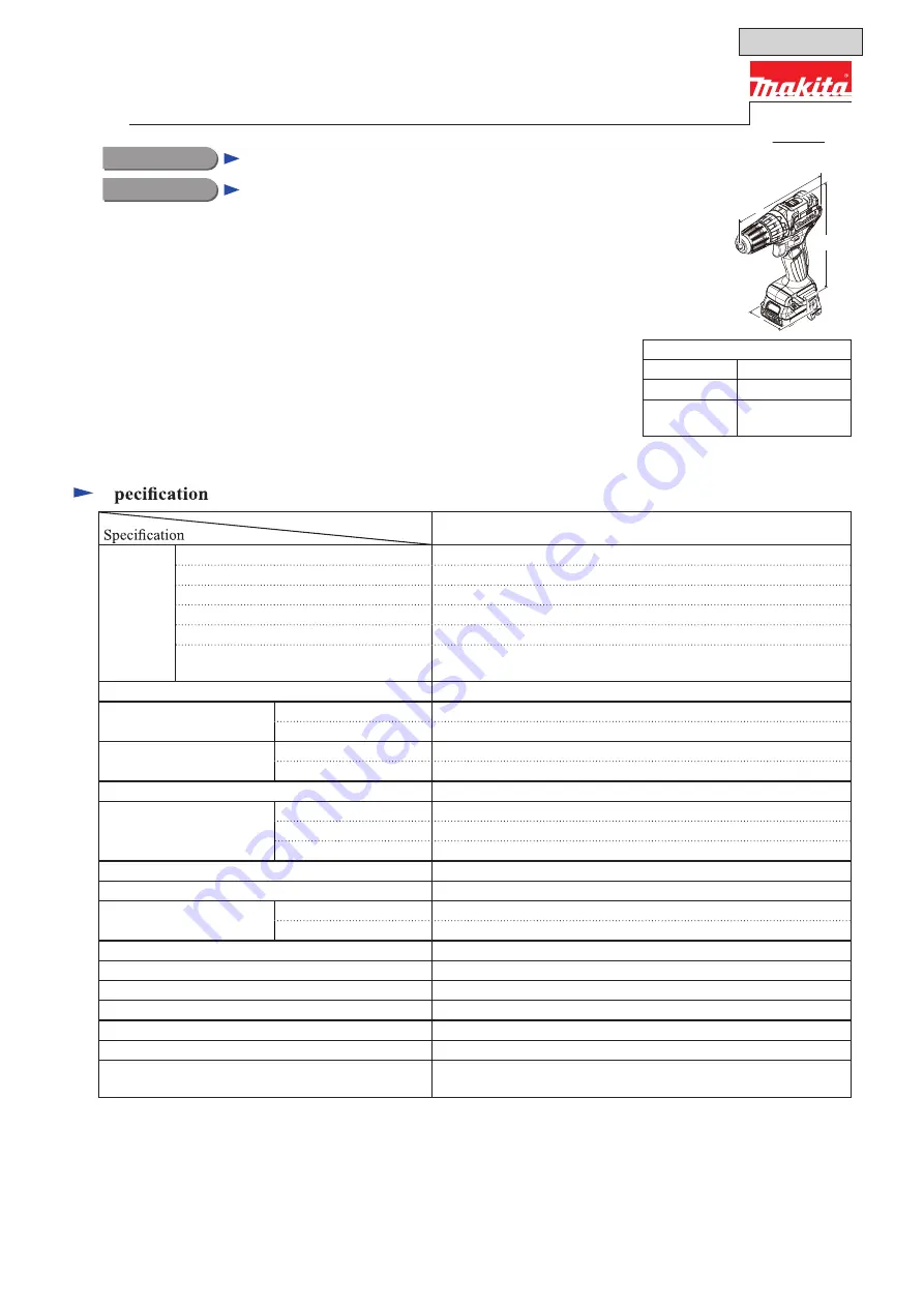
Dimensions: mm ( " )

Length (L)

168 (6-5/8)

Width (W)

66 (2-5/8)

Height (H)

217 (8-1/2)

*

or

 236 (9-1/4)

*

2

L

W

H

*1

With battery BL1015; BL1020B

*2

With battery BL1040B

T

ECHNICAL INFORMATION

PRODUCT

P 1/ 20

Model No.
Description

Cordless Hammer Driver Drill

HP332D

December 2015

OFFICIAL USE 

for ASC & Sales Shop

Summary of Contents for HP332D

Page 1: ...ity of drill chuck mm 0 8 1 32 10 3 8 Capacity mm Masonry 8 5 16 Steel 10 3 8 Wood 28 1 1 8 Torque setting 20 stages drill mode Clutch torque setting N m in lbs 1 0 9 5 0 44 Max tightening torque N m...

Page 2: ...Note The standard equipment may vary by country or model variation 3For all countries except North Central and South American countries Asia Australia 4For North Central and South American countries A...

Page 3: ...wever in case of trouble on Gears replace Gear assembly as an assembly parts PLATE SET WITH SCREWS 1R231 Removing drill chuck for DF332D HP332D Removing drill chuck for DF332D HP332D Removing Mounting...

Page 4: ...by disassembling Gear assembly 9 Be careful not to damage head of Screw or Bolt when unscrewing Because Locktite 272 is applied to its thread A Removing with Hex wrench and Hammer 3 Insert short arm s...

Page 5: ...W450 See the upper photograph in Fig 5 2 Inserting another end of 1R231 into Keyless Drill chuck 10 9 grip it with the Drill chuck 9 See the lower photograph in Fig 5 3 Hold the machine to be repaired...

Page 6: ...he work bench and separate Keyless drill chuck 10 9 from Gear assembly 11 3 Gear assembly 11 can be disassembled as illustrated in Fig 9 And take out Carrier complete e to use it as a jig for separati...

Page 7: ...by fitting pin portion to the socket hole See Fig 11 6 Set Keyless drill chuck 10 9 to Carrier complete e inserting Spindle into Carrier complete e See left photograph in Fig 12 7 Attach 1R231 to Bit...

Page 8: ...gear 15 3 pcs o Ring gear 44 p Motor washer q Grease cover R r Pin 1 5 2pcs s Rear housing t Grease cover L u Speed change shifter j s Front housing Front housing 2 Keep Gear assembly of Drill chuck...

Page 9: ...sembly 11 See lower left illustration in in Fig 16 11 1 3 3 11 2 Set the machine to Drill mode 3 Inserting the long arm side of Hex wrench 8 grip it with Keyless drill chuck See fig 17 9 Long arm of H...

Page 10: ...6 Tapping screws See the left photograph in Fig 20 3 Set Speed change lever 4 to 2 See the right illustration in Fig 20 1 Disassemble Keyless drill chuck 10 selecting any of the followings measures as...

Page 11: ...rive end of Rotor 15 to work bench See the left photograph in Fig 23 8 Pressing down Stator 14 toward work bench pull off Rotor 15 See the right illustration in Fig 23 15 14 drive end Right handling s...

Page 12: ...protruded portion of housing set L 17 See Fig 26 1 Insert Rotor 15 into Stator 14 while being careful to the following points Hold the Fan portion to avoid pinching your finger with Rotor fan and edg...

Page 13: ...shifter in the direction designated with black arrow So Speed change shifter has been set to 2 5 Fitting the grooved portion of Change lever assembly 10 to Speed change shifter mount Speed change lev...

Page 14: ...nent parts of Bit holder section are removed as follows 18 Steel ball 3 2 pcs 19 Bit sleeve 20 Compression spring 13 21 Bit washer 22 Ring spring 10 See Fig 30 1 Mount 2 pcs of Steel ball 3 and then a...

Page 15: ...ange lever assembly 10 See Fig 32 Compression spring s one role fitting to the rib of Change lever assembly 2 Mount Change lever assembly 10 to Speed change lever by fitting the grooved portion to the...

Page 16: ...ield effect transistor of Controller can be checked with Tester as follows See Fig T 2 Fig T 2 1 Set 1R402 A Tester to diode mode 2 Removing Battery lock Switch lever to ON position for example by bun...

Page 17: ...ive actions Yes No No No No No Replace Controller The machine does not have any trouble Rotor is broken Stator is broken Replace Stator Replace Rotor Replace Controller Breakage of Controller Disconne...

Page 18: ...ed Controller Terminal Flag connector with lock Flag connector with lock Bullet terminal Connector Symbol of Electrical Parts A A B B C D D D C C AWG 22 AWG 22 AWG 16 AWG 22 AWG 16 AWG 16 AWG 16 UL326...

Page 19: ...he inner wall of Housing set L Bullet terminal 3 pcs Stator Switch Controller Put lead wires of LED light circuit between Rib A and Boss A and guide them through the route between Rib C and Rib A Bull...

Page 20: ...it is connected to the lead wires of Controller Controller Controller Twisted wire Twisted wire Non insulated sleeve Poly olefin tube at least 2 mm Non insulated sleeve Non insulated sleeve Wiring of...

Reviews: