background image

P 1

2

/ 1

2

W

iring diagram

Wiring to Switch

Connect Lead wires to Switch, tilting their 

Connectors to 45 degrees as dran below.

FET

Fix FET Lead wires as follows:

yellow

 with Lead wire holder 

nearest to

 Switch trigger

blue

 with the 

center

 Lead wire holder

black

 with Lead wire holder 

farthest


from

 Switch trigger

Lead wire

holder

yellow

blue

black

 Switch trigger

FET

Fig. D-4A

Fig. D-5A

Wiring in Housing set (L)

 Seal

Put the bundled Lead wires

into the groove of Sponge.

Pay attention not to put 

Lead wires on the Seal.

Lead wires connected to

Connector have to be fixed

with Lead wire holders.

45 degrees

without Battery fuel gauge 

available exclusively for 

North American countries

Brush holder complete

Put Pigtail of Carbon brush 

in the area marked with gray 

color to avoid pinching with 

Rear cover. 

Pigtail of Carbon brush

9 mm

9 mm

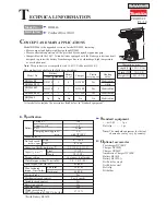
Summary of Contents for BHP448

Page 1: ...ng variations PRODUCT Housing color BHP448RFE DC18RC Model No Type Quantity Charger Plastic carrying case Battery cover Yes 2 Battery BL1430 1 No No No No No BHP448Z Makita blue BHP448RFE3 DC18RC Yes...

Page 2: ...h 10 Use this tool if Drill chuck cannot be removed by the method of described in 3 1 Drill chuck disassembling removing mounting Drill chuck Open Drill chuck fully and remove M6x22 Flat head screw by...

Page 3: ...chuck in place Fig 7 M6x22 Flat head screw Left handed thread Turn Drill chuck clockwise by hand until it sits on the end of the threaded portion of Spindle Note Apply adhesive ThreeBond 1321B 1342 or...

Page 4: ...essed by the lever of Gear assembly Drill chuck side Motor side Drill chuck side Motor side 5 Push Speed change lever assembly toward Motor side until it stops to have space between the pin on the lev...

Page 5: ...rew to Yoke unit And insert the Motor section into Gear assembly while engaging Armature s gear with the Planet gears in Gear assembly Refer to the center right drawing in Fig 8 4 Before mounting Spee...

Page 6: ...sion spring 4 of Speed change lever assembly to the flat side without pin of Gear assembly for Speed change 2 Push Speed change lever assembly toward Motor side until it stops to have space between pi...

Page 7: ...ve any damage on Housing set when holding with Water pump pliers Gear case assembly The flat portion of Brush holder complete must be at 90 degrees to the edge surface of Housing L flat portion of Bru...

Page 8: ...ousing L as drawn below Projection Prong ASSEMBLING 3 4 Switch plate complete ASSEMBLING Put the projection on Switch between the prongs of F R change lever Fig 15 Fig 15 Housing L Switch plate comple...

Page 9: ...Switch Red Lead wire is used for some countries instead of white Terminal LED Wire connecting portion Fix LED lead wires with Lead wire holders drawn below Wiring of LED Lead Wires before setting Swi...

Page 10: ...yellow blue black Switch trigger Fig D 4 Fig D 5 Line filter Seal Put Line filter in this place Sponge Put the bundled Lead wires into the groove of Sponge Pay attention not to put Lead wires on the...

Page 11: ...D Switch Terminal Fig D 2A Fig D 1A LED Wire connecting portion Fix the LED lead wires with Lead wire holders drawn below Wiring of LED Lead Wires before setting Switch Wiring to Terminal Lead wire ho...

Page 12: ...ire holder yellow blue black Switch trigger FET Fig D 4A Fig D 5A Wiring in Housing set L Seal Put the bundled Lead wires into the groove of Sponge Pay attention not to put Lead wires on the Seal Lead...

Reviews: