background image

MyPower VG2000 V4 VoIP Gateway Installation Manual

Page

25 / 72

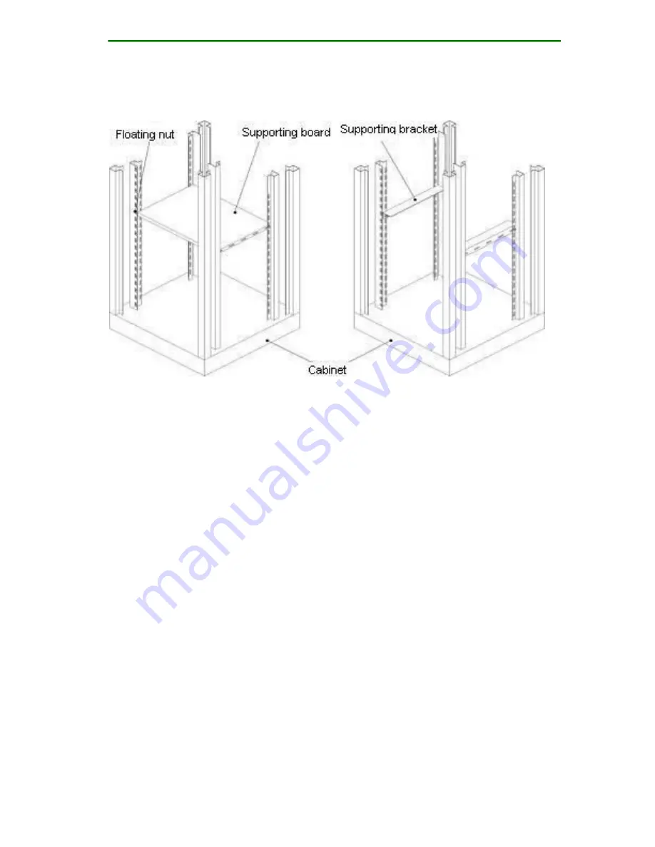
Figure 3-4 Cabinet diagram

Check whether the floating nut of the fixed device is
already installed in the square hole of the cabinet upright
post. If not, install the floating nut to the corresponding
square hole based on the supporting board or supporting
bracket location. Generally, a device should be placed on a
supporting board or supporting bracket. It is not
recommended to place multiple devices overlap each
other.

Step 2: Install the cabinet bracket of the MyPower
VG2000-32S VoIP gateway.

Wear the glove and ESD wrist strap and connect the ESD
wrist strap to the ground reliably.

Place the device on a fixed platform horizontally. Aim the
supporting bracket installation hole to the corresponding

Summary of Contents for MyPower VG2000

Page 1: ...Manual Maipu Communication Technology Co Ltd No 16 Jiuxing Avenue Hi tech Park Chengdu Sichuan Province People s Republic of China 610041 Tel 86 28 85148850 85148041 Fax 86 28 85148948 85148139 URL h...

Page 2: ...e 1 72 Copyright 2015 Maipu Communication Technology Co Ltd All Rights Reserved No part of this manual may be reproduced or transmitted in any form or by any means without prior written consent of Mai...

Page 3: ...2000 series VoIP gateway Audience This documentation is intended for Network engineers Technical marketing personnel Network administrator Introduction This manual mainly introduces the hardware feat...

Page 4: ...to the preceding figure Statement The information in this document is subject to change without notice Every effort has been made in the preparation of this document to ensure accuracy of the contents...

Page 5: ...ription 12 2 1 3 POTS FXS Port Description 13 2 2 Mechanical Installation 13 2 2 1 Cabinet Installation 13 2 2 2 Ground Requirement 17 2 2 3 Power Connection 18 2 3 Cable Connection 19 2 3 1 Console C...

Page 6: ...n 42 4 3 2 Ethernet Cable Connection 43 4 3 3 Module Cable Connection 43 5 VG2000 48S Installation 46 5 1 Hardware Features 46 5 1 1 MyPower VG2000 48S Appearance 46 5 1 2 MyPower VG2000 48S Front Pan...

Page 7: ...ment 62 6 2 3 Power Connection 62 6 3 Cable Connection 64 6 3 1 Console Cable Connection 64 6 3 2 Ethernet Cable Connection 65 6 3 3 POTS FXS Cable Connection 65 7 Cable Description 66 7 1 Ethernet Ca...

Page 8: ...humidity in the equipment room It is good for protecting the line and extending the VoIP gateway life The VG2000 series VoIP gateway must be used indoors The VG2000 series VoIP gateway has the requir...

Page 9: ...within 5h 1 1 2 Cleanliness Requirement Dust is harmful for the VG2000 series VoIP gateway operation Dust causes electrostatic absorption which makes the poor contact of metal connectors Electrostati...

Page 10: ...nce including grounding system and lead such as power lines signal lines and output lines Therefore pay attention to the following Take valid anti grid disturbance measures for the power system The wo...

Page 11: ...re complete by the order 1 3 Required Tools and Devices 1 Tools Phillips screwdriver Level ruler or tapeline Gloves and ESD wrist strap 2 Connected cables Cables in the package 3 Devices Configuration...

Page 12: ...er VG2000 16 Appearance Figure 2 1 MyPower VG2000 16 appearance diagram The feature parameters of MyPower VG2000 16 VoIP gateway are described in the following table Storage FLASH 16M Bytes DDR2 SDRAM...

Page 13: ...panel diagram of the MyPower VG2000 16 VoIP gateway The indicators on the figure from left to right respectively are PWR Power indicator always on state indicates that the power works normal and othe...

Page 14: ...e MyPower VG2000 16 VoIP gateway to the 19 inch standard cabinet When the cabinet is unavailable you can place the device horizontally on the clean plane Keep at least 10cm space around the device to...

Page 15: ...ies contact the cabinet supplier to provide the original accessories The device must be installed on the supporting board or supporting bracket using in pair of the cabinet Therefore install the suppo...

Page 16: ...cabinet upright post If not install the floating nut to the corresponding square hole based on the supporting board or supporting bracket location Generally a device should be placed on a supporting...

Page 17: ...de of the device faces the handler Use hands to stably hold the device and keep the device horizontally Carefully place the device on the supporting bracket or supporting board from the front side of...

Page 18: ...two devices to ensure the heat dissipation space for the device Install the blank panel configured for the cabinet in the space between two devices 2 2 2 Ground Requirement The ground requirements for...

Page 19: ...socket or multi functional microcomputer power socket is recommended The earth line of the power must be grounded well Generally when laying out the cables the earth line of the building power supply...

Page 20: ...peat setpe1 to step 2 Note If the power indicator is still off after repeating the preceding steps contact the agent 2 3 Cable Connection 2 3 1 Console Cable Connection Console cable model C1223 1032...

Page 21: ...thernet cable to the HUB switch PC or other network devices Note Check the identifier on the interface during connection to avoid module or VG2000 16 VoIP gateway host damage by inserting other interf...

Page 22: ...nce Figure 3 1 VG2000 32S appearance diagram The feature parameters of MyPower VG2000 32S VoIP gateway are described in the following table Storage FLASH 16M Bytes DDR2 SDRAM 64M Bytes Fixed Configura...

Page 23: ...front panel is as follows PWR Power indicator always on state indicates that the power works normal and other states indicates that the power does not work or works abnormally SYS The indicator flash...

Page 24: ...VoIP gateway to the 19 inch standard cabinet When the cabinet is unavailable you can place the device horizontally on the clean plane Keep at least 10cm space around the device to ensure enough heat d...

Page 25: ...ies contact the cabinet supplier to provide the original accessories The device must be installed on the supporting board or supporting bracket using in pair of the cabinet Therefore install the suppo...

Page 26: ...n the supporting board or supporting bracket location Generally a device should be placed on a supporting board or supporting bracket It is not recommended to place multiple devices overlap each other...

Page 27: ...ing VG2000 32S VoIP gateway to the cabinet The front side of the device faces the handler Use hands to stably hold the device and keep the device horizontally Carefully place the device on the support...

Page 28: ...avity to improve stability When installing the device in the cabinet it is recommended to keep 1U space between two devices to ensure the heat dissipation space for the device Install the blank panel...

Page 29: ...the MyPower VG2000 32S VoIP gateway has a large tolerance for the input power The following power socket or multi functional microcomputer power socket is recommended The earth line of the power must...

Page 30: ...gateway to the ON location Step 3 Check whether the power indicator on the front panel of the MyPower VG2000 32S VoIP gateway is on If not repeat setpe1 to step 2 Note If the power indicator is still...

Page 31: ...to FE0 or FE1 Ethernet interface Step 2 Connect the other end of the Ethernet cable to the HUB switch PC or other network devices Note Check the identifier on the interface during connection to avoid...

Page 32: ...G2000 32 Installation 4 1 Hardware Features 4 1 1 MyPower VG2000 32 Appearance Figure 4 1 MyPower VG2000 32 appearance diagram The feature parameters of MyPower VG2000 32 VoIP gateway are described in...

Page 33: ...phone interface 4 channel FXO switch interface E1 interface module Support 1 channel E1 interface Dimension W x D x H 440 mm x 300 mm x 44 5 mm Work Temperature 0 40 Work Humidity 10 90 non condensin...

Page 34: ...that the fast Ethernet link is connected and indicator off indicates that the link is not connected Rx Tx RJ45 right indicator flash indicates that the fast Ethernet interface can normally receive an...

Page 35: ...tandards Ring current 25HZ 48PPV The change of the gain with the frequency the change of the gain with the input level total distortion idle channel noise outband and inband noise secondary and third...

Page 36: ...le Interface Parameter of 4S4O Interface Module Current 0 110mA DC load impedance 300 Enable voltage of ring detection 23V frequency range 15 75Hz Line impedance The return loss meets the G 712 and Q...

Page 37: ...f E1 Interface Module The connection cable of the E1 module is CAB1E1 RJ45M 2BNCM One end is RJ45 connector and the other end is BNC connector Interface Parameter of E1 Interface Module Conform to ITU...

Page 38: ...ing the device Use a ruler or tapeline to measure the horizontal installation hole center distance and horizontal direction installation net space of the cabinet The size should comply with the follow...

Page 39: ...ting board or supporting bracket is horizontal If not please adjust the fixed bolt of the supporting board or supporting bracket to make them horizontal and then tighten the bolt Figure 4 7 Cabinet di...

Page 40: ...nds to stably hold the device and keep the device horizontally Carefully place the device on the supporting bracket or supporting board from the front side of the cabinet Please avoid the device and c...

Page 41: ...onfigured for the cabinet in the space between two devices 4 2 2 Grounding Requirement The ground requirements for the upper bracket and device with ground pole are as follows The ground mode should b...

Page 42: ...l Generally when laying out the cables the earth line of the building power supply system is already buried underground The user should check whether the building power is grounded reliably Otherwise...

Page 43: ...ng steps contact the agent 4 3 Cable Connection 4 3 1 Console Cable Connection Console cable model C1223 1032 Connect the cable by the following steps Step 1 Prepare a PC or compatible PC with standar...

Page 44: ...HUB switch PC or other network devices Note Check the identifier on the interface during connection to avoid module or VG2000 32 VoIP gateway host damage by inserting other interfaces Check the host p...

Page 45: ...5 and the other end is 8 core twisted pair cable 2 4S4O interface module Support four FXS interfaces and four FXO interfaces Insert card of 4S4O VoIP module RJ45 transfer cable One end of the transfe...

Page 46: ...MyPower VG2000 V4 VoIP Gateway Installation Manual Page 45 72 the other end is coaxial cable...

Page 47: ...rdware Features 5 1 1 MyPower VG2000 48S Appearance Figure 5 1 MyPower VG2000 48S appearance diagram The feature parameters of MyPower VG2000 48S VoIP gateway are as follows Storage FLASH 16M Bytes DD...

Page 48: ...y 50 60Hz 5 1 2 MyPower VG2000 48S Front Panel Figure 5 2 MyPower VG2000 48S front panel diagram The description of the indicators on the front panel is as follows PWR Power indicator always on state...

Page 49: ...ndicator 5 1 3 POTS FXS Port Description The device provides 12 RJ45 interfaces and each RJ45 interface supports 4 FXS used to connect the telephone terminal 5 2 Mechanical Installation 5 2 1 Cabinet...

Page 50: ...ply with the following figure Figure 5 3 Cabinet dimension Check whether the supporting board and bracket floating nut fixed screw and blank panel of the cabinet are complete which are standard access...

Page 51: ...t to make them horizontal and then tighten the bolt Figure 5 4 Cabinet diagram Check whether the floating nut of the fixed device is already installed in the square hole of the cabinet upright post If...

Page 52: ...porting board from the front side of the cabinet Please avoid the device and cabinet upright post collision during placing Step 4 Push the device using two hands and keep the supporting bracket of the...

Page 53: ...hould be in accordance with the joint ground mode of the work ground protection ground and building lightning protection ground sharing the same ground body Ground line sectional area ground line sect...

Page 54: ...nding processing The following figure shows the shapes of common power sockets Figure 5 5 Power socket Connect the power by the following steps Step 1 After the MyPower VG2000 48S VoIP gateway power s...

Page 55: ...Step 2 When either MyPower VG2000 48S VoIP gateway or PC is power down connect the console cable respectively to the RS 232 serial port of the PC and the console port of the MyPower VG2000 48S VoIP ga...

Page 56: ...the interface during connection to avoid module or VG2000 48S VoIP gateway host damage by inserting other interfaces Check the host panel indicator state when the system enters the normal work state T...

Page 57: ...rdware Features 6 1 1 VG2000 64S Appearance Figure 6 1 VG2000 64S appearance diagram The feature parameters of VG2000 64S VoIP gateway are as shown in the following table Storage FLASH 16M Bytes DDR2...

Page 58: ...6 1 2 VG2000 64S Front Panel Figure 6 2 VG2000 64S front panel diagram The description of the interfaces and indicators on the front panel is as follows PWR Power indicator always on state indicates...

Page 59: ...16 RJ45 interfaces and each RJ45 interface supports 4 FXS used to connect the telephone terminal 6 2 Mechanical Installation 6 2 1 Cabinet Installation It is recommended to install the MyPower VG2000...

Page 60: ...complete which are standard accessories of the cabinet The accessory size or shape varies with different cabinets Therefore for the cabinet accessories contact the cabinet supplier to provide the ori...

Page 61: ...ight post If not install the floating nut to the corresponding square hole based on the supporting board or supporting bracket location Generally a device should be placed on a supporting board or sup...

Page 62: ...arefully place the device on the supporting bracket or supporting board from the front side of the cabinet Please avoid the device and cabinet upright post collision during placing Step 2 Push the dev...

Page 63: ...ding Requirement The ground requirements for the upper bracket and device with ground pole are as follows The ground mode should be in accordance with the joint ground mode of the work ground protecti...

Page 64: ...derground The user should check whether the building power is grounded reliably Otherwise the user should do corresponding processing The following figure shows the shapes of common power sockets Figu...

Page 65: ...odel C1223 1032 Connect the cable by the following steps Step 1 Prepare a PC or compatible PC with standard RS 232 serial port Step 2 When either MyPower VG2000 64S VoIP gateway or PC is power down co...

Page 66: ...HUB switch PC or other network devices Note Check the identifier on the interface during connection to avoid module or VG2000 64S VoIP gateway host damage by inserting other interfaces Check the host...

Page 67: ...7 Cable Description 7 1 Ethernet Cable The Ethernet interface cable of the VG2000 series VoIP gateway is 8 core unshielded twisted pair Table 7 1 Straight through Ethernet cable connection relationshi...

Page 68: ...blue 5 blue and white 5 blue and white 7 brown 7 brown 8 brown and white 8 brown and white Table 7 2 Cross Ethernet cable connection relationship table model C1212 1003 RJ45 Interface Signal Directio...

Page 69: ...Page 68 72 8 brown and white 8 brown and white The preparation of the cross and straight through Ethernet cable is as follows Figure 7 1 Diagram of preparing the cross Ethernet cable Figure 7 2 Diagra...

Page 70: ...ector and the other end is a DB 9 female plug Table 7 3 Console port cable connection relationship table model C1223 1032 RJ45 Interface Signal Direction DB9 Interface 1 CTS 8 2 DSR 6 3 RXD 2 4 GND 5...

Page 71: ...MyPower VG2000 V4 VoIP Gateway Installation Manual Page 70 72 Figure 7 3 The connection cable diagram of FXS FXO interface module...

Page 72: ...ateway to avoid serious damage caused by device falling Properly laying out the cable Do not place any heavy things on the power cable and avoid stepping on the connection cable Do not hot plug the po...

Reviews: