background image

46

Mahr GmbH • Digimar 817 CLM

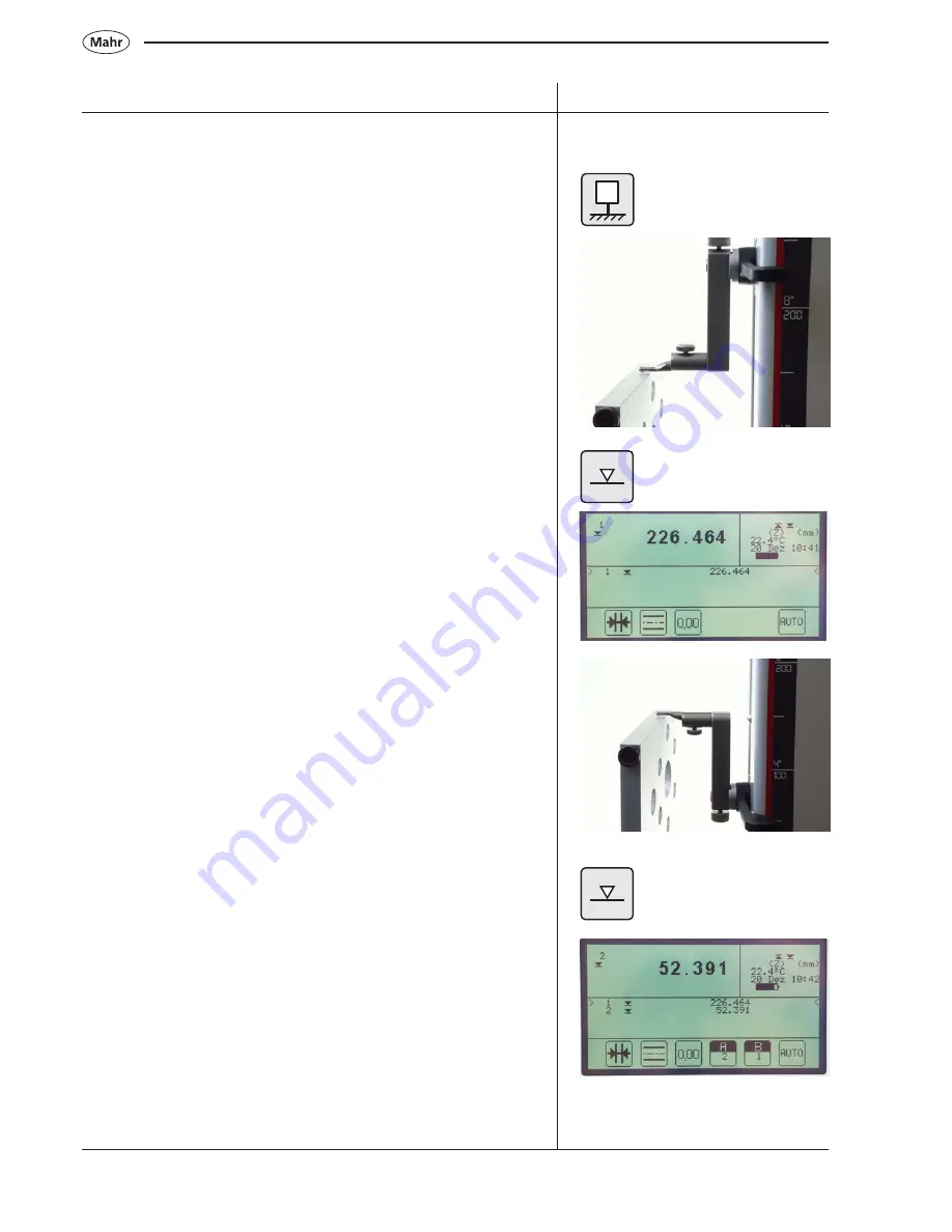
4.2.7 Expanding the measuring range

Basis-zero point, base plate

Use either a gage block or a predetermined workpiece that is

larger

than 180 mm.

The probe moves downwards and contacts the gage block or
workpiece.

Loosen the clamping screw and turn the probe holder around

180°.

Then tighten the clamping

screw back into position.

The probe moves downwards and contacts the gage block or
workpiece.

Description / Sequence

Symbols / Pictures

0

Summary of Contents for Digimar 817 CLM

Page 1: ...ight Height Measuring Instrument Operating instructions 3759019 Version 1 02 30 en Mahr GmbH Esslingen D 73702 Esslingen Postfach 10 02 54 Telefon 07 11 9 31 26 00 Fax 07 11 9 31 27 25 e mail mahr es...

Page 2: ...uires the express written approval of Mahr GmbH and must be carried out by qualified personnel Unauthorized opening of the height measuring instrument and unauthorized intervention invalidates the war...

Page 3: ...ement procedure with the function keys 28 3 2 Start a measurement procedure in Quick Mode 31 3 3 Start a measurement procedure with the speed keys 34 3 4 Abort a measurement 35 4 Operation and measuri...

Page 4: ...4 5 4 Determine the distance and angle between 3 elements 61 4 5 5 Index circle best fit circle 64 4 5 6 Coordinate transformation aligning the workpiece arithmetically 66 4 6 Measuring a taper calcul...

Page 5: ...ection table 97 6 14 6 3 Customer specified correction table 97 6 14 6 4 Create a new correction table Z 97 6 14 6 5 Print a correction table 97 6 14 6 6 Perpendicularity correction table 98 6 14 6 7...

Page 6: ...0 1 Software update 129 10 2 Initialization of the internal memory 131 10 3 Storing additional languages 132 10 4 Customer calibration 134 11 Self help maintenance and care 11 1 Troubleshooting 140 11...

Page 7: ...1 Delivery and setting up 1 1 Scope of supply C K M6 L M4 3x M 3 mm N 4 mm O 5 mm G H 2D MAX MIN DISP STAT PROG CONFIG CAL DATA CE ON OFF 1 2 3 4 5 6 7 8 9 0 ABC DEF GHI JKL MN O PQRS TUV WXYZ Quick...

Page 8: ...8 Mahr GmbH Digimar 817 CLM 1 2 Unpacking 1 2 N I C K L M O P Q...

Page 9: ...9 Mahr GmbH Digimar 817 CLM 3 4 2D MA X MIN DISP STA T PROG CONFIG CAL DATA CE ON OFF 1 2 3 4 5 6 7 8 9 0 ABC DEF GHI JKL MN O PQR S TUV WXYZ Quick 0 Height D E F G H B J...

Page 10: ...10 Mahr GmbH Digimar 817 CLM 5 350 mm 25 kg 600 mm 30 kg 1000 mm 35 kg...

Page 11: ...11 Mahr GmbH Digimar 817 CLM 6 45 7 8 90...

Page 12: ...12 Mahr GmbH Digimar 817 CLM 9 11 G H 10 12 13 M...

Page 13: ...13 Mahr GmbH Digimar 817 CLM B 3x L M 19 17 18 P D E K N 14 15 16...

Page 14: ...14 Mahr GmbH Digimar 817 CLM 100 240 V 50 60 Hz I 12 h 21 22 Euro US UK 20 23...

Page 15: ...the measuring column HEIGHT 6 LED display GAGE 7 Handle for manually moving the slide 19 Interface connection for digital indicators INPUT 1 8 Control and evaluation unit required for perpendicularit...

Page 16: ...M 1 3 2 Keypad Measuring function keys Variable function keys Calibration and set up function keys Delete and accept function keys Keypad Active deactive the Quick Mode Arrow keys Evaluation function...

Page 17: ...e chapter 7 Statistics functions See chapter 8 Calibrate a probe See chapter 4 1 Zero point See chapter 4 2 Menu settings See chapter 6 Data transmission select data for transmission See chapter 9 1 D...

Page 18: ...l enter a subdirectory lower level The different meanings are described in the operating instructions 1 3 2 6 Input pad Each key is assigned a multiple character function by repeatedly pressing a key...

Page 19: ...ic number Characteristic symbol Actual character Display field Stored measured values Charging condition of the battery Date and time Unit of measurement 2 D Mode is activated Actual axis Quick Mode p...

Page 20: ...connect either a PC or statistics printer RS 232 Interface Input 1 To connect a digital indicator required for perpendicularity checks SUB D Interface15 pin To connect an incremental probe required f...

Page 21: ...e position Perpendicularity 2D selection key Zero point Select data for transmission ON OFF Confirm Statistics function 2D 0 DATA Contacting a plane surface from below Measuring a bar Measuring a shaf...

Page 22: ...ect horizontal probe Travel upwards Contacting a bar from above 1 3 5 2 Symbols function keys Calculating the symmetry between 2 planes Automatic calculation of the distance Zero point last measured v...

Page 23: ...the tilting angle with a probe Rotate anti clockwise Set Z value to zero Set the zero point on the base plate Work piece zero point 02 Enter Preset Direct select data transmission Store on internal m...

Page 24: ...straightness graphic curve Accept the minimum value Bar graph Error character number X Deactivate 2D Change the production data Taper probe 1 3 5 3 Symbols display Bore from above Bore from below Sha...

Page 25: ...when updating the software the following questions the basic settings will appear 2 2 Basic settings These can be selected by using the arrow keys confirm by pressing the Enter key Enter the time and...

Page 26: ...ny zero point can be selected 2 4 Calibrating a probe a Press the calibrate probe key b Press the function key Calibrate in a groove the probe moves automatically to the center of the groove of the se...

Page 27: ...section of the display will appear the measured value 2 5 Auto Off function In the basic setting mode the background lit display switches off after 1 minute by pressing any key the background lit dis...

Page 28: ...ment must then is moved so that the measuring instrument can determine an extreme value When measuring with 2 contacts e g a bore groove or shaft the first contact must be upwards from below Function...

Page 29: ...ce in order to determine the reversal point maximum Acceptance of the reversal point will be confirmed by an acoustic signal beep The probe will automatically travel downwards the bore is contacted fr...

Page 30: ...ceptance of the reversal point will be confirmed by an acoustic signal beep Position the probe above the shaft eccentrically Press the function key Contacting a shaft from above The probe will automat...

Page 31: ...of measuring The operator can conduct for example chain measurements or measurement upon several bores e g calculation of a index circle extremely efficiently and fast Description Sequence Symbols Pi...

Page 32: ...asuring function Once contact has been made and the measured value has been accepted this is confirmed by an acoustic signal beep and the value appears in the display 2 1 2 1 3 2 3 2 Contacting a plan...

Page 33: ...orkpiece parallel to the stopping face in order to determine the reversal point maximum Acceptance of the reversal point will be confirmed by an acoustic signal beep The probe moves automatically down...

Page 34: ...will be emitted beep and the measured value will be shown in the display 3 3 3 Switching between contacting a plane bore Press the shift key on the base plate If the Contact a plane is active the fol...

Page 35: ...3 Position the probe into the bore the probe must be off set To start measurement briefly press the speed key 0 5 s contact from below upwards 0 5 s contact from above downwards 3 4 Abort a measureme...

Page 36: ...x 2 When calibrating the probe it will automatically travel to the preset height of the gage block this value can be changed in the probe calibration menu See chapter 6 14 3 Probe calibration paramete...

Page 37: ...Position the vertical probe above the ledge Press the function key Calibrate vertical probe The measured value is automatically accepted Position the horizontal probe above the ledge Press the functio...

Page 38: ...r a second time below the ledge the probe moves upwards and makes contact Position the probe for a second time above the ledge the probe moves downwards and makes contact Note When calibrating with a...

Page 39: ...ucted measurement The following function keys appear Conduct calibration once more the average mean value will be calculated from the previous determined probe constant and the newly measured constant...

Page 40: ...the base plate the zero point is set 4 2 Zero points The workpiece zero point can be set only on an already determined characteristic Basic zero point base plate Workpiece zero point 01 Workpiece zer...

Page 41: ...int 01 Contact a plane Press zero point key Press the function key Workpiece zero point 01 By several characteristics the selection can be made using the arrow keys Confirm by pressing the A key Workp...

Page 42: ...piece zero point 02 are the set after zero point 01 Contact a plane Press the Zero point key Press the function key Workpiece zero point 02 Use the arrow keys to make a selection Note The characterist...

Page 43: ...piece zero point 03 Follow the same procedure as setting workpiece zero point 02 4 2 5 Switching between the zero points By pressing the 01 02 key you can change between the set zero points In the dis...

Page 44: ...is sufficient from 100 mm to 700 mm with an height measuring instrument with a 600 mm measuring path Note Refer to 4 2 7 extension of the measuring range Contact a plane Press the Zero point key Press...

Page 45: ...lue 50 000 mm will change to 150 000 mm When measuring a 100 000 mm gage block the height measuring instrument will show 200 000 mm in the display Note Reset the actual Preset value by pressing the ze...

Page 46: ...mined workpiece that is larger than 180 mm The probe moves downwards and contacts the gage block or workpiece Loosen the clamping screw and turn the probe holder around 180 Then tighten the clamping s...

Page 47: ...ursor to select characteristics 2 Confirm by pressing the function key characteristic Use the keypad to enter the actual size Press the Preset key Confirm by pressing the ON OFF key To check move the...

Page 48: ...2 means that 02 must have a higher characteristic number than 01 Index 03 means that 03 have a higher characteristic number than 01 or 02 4 2 9 Further zero point functions Please refer to Chapter Var...

Page 49: ...tion Quick Mode Speed keys key 4 3 1 Contact from above plane 0 5 Sec 4 3 2 Contact from below plane 0 5 Sec 4 3 3 Determine the center of a ledge and the width of the ledge 4 3 4 Determine the center...

Page 50: ...own in the display Function Quick Mode Speed keys key 4 3 5 Determine the center of a bore and the diameter of the bore 4 3 6 Determine the center of a shaft and the diameter of the shaft 4 3 7 Contac...

Page 51: ...Quick Mode settings is set to automatic recognition of plane bore Contact from below to determine the reversal point minimum only available when Quick Mode settings is set to automatic recognition of...

Page 52: ...ars in the display and shows the actual value Cancel the MAX MIN function print out the displayed values Display Maximum Minimum Select minimum value maximum value Display Accept the maximum minimum v...

Page 53: ...d Depending upon the speed and the measuring instrument 350 600 1000 mm the number of measuring points and the set measuring track can alter accordingly Mount the probe into the holder on the measurin...

Page 54: ...the measuring path Only positive values are possible Start measurement by pressing Stop measurement by pressing Select Graphic for perpendicularity error Graphic for straightness To interrupt the mea...

Page 55: ...USB printer 4 Save all measuring points USB memory 5 6 Abort Once the perpendicularity error has been evaluated you can additionally show the straightness error as a value M 1 2 3 4 5 6 max 6 5 7 4 1...

Page 56: ...onduct all the usual 2D measuring tasks as for example the computation of index circle bestfit circle or angles and distances between bore holes In addition the measured values of both Z axis and X ax...

Page 57: ...either entered via the keypad or measured directly with an incremental probe Note The more accurate the given tolerance is for the measuring values thus the tilting angle must also be more accurate Ti...

Page 58: ...hmetically Deactivate the 2D mode Tilt the workpiece 4 5 1 Manually enter a tilting angle Active the 2D key Select Manually enter the tilting angle Calculate tilting angle Active 2D Tilt workpiece Man...

Page 59: ...iece Measure the tilting angle The following menu appears in the determination of the perpendicularity error See chapter 4 4 2 Measuring the perpendicularity error The following menu will appear Accep...

Page 60: ...igned at 90 Measure the bore holes 1 2 in exactly the same procedure in the X axis Tilt the workpiece back into its original position Active the distance and angle between 2 elements function Descript...

Page 61: ...istic whose number is in the middle of the three numbers The origin of the angle is therefore lies in the center second characteristic The operator can select between the internal and the external ang...

Page 62: ...cription Sequence Symbols Pictures z x a 2D ON z x Select a bore hole If several bore holes are to be measured select the characteristics using the arrow keys and adopt them using the characteristic A...

Page 63: ...it the 2D function Confirm Use the arrow keys to move to the required results select with the cursor and accept the result by pressing the ON OFF key ON OFF Use the arrows key to select further result...

Page 64: ...817 CLM can calculate Press CE to delete all data Press the 2D key Active 2D Measure bores 1 3 in the Z axis At first the display indicates the Z values and subsequently the diameter Tilt the workpiec...

Page 65: ...allocation has been given The numbers of measured bores are different in each axis The index circle is calculated from the center of the 3 bore holes Adding the characteristics bore holes shafts to be...

Page 66: ...in the center of the element that was selected first The X axis abscissa runs through the centers of the selected elements The Z axis is with the first characteristic intersects perpendicular to the X...

Page 67: ...ores 1 4 in exactly the same sequence as with the X axis Tilt the workpiece back into the original position In the display appears the Z value and the X value Description Sequence Symbols Pictures z x...

Page 68: ...lockwise Select the type of rotation for the coordinate system 1 The transformation will be conducted without rotation of the coordinates system Description Sequence Symbols Pictures Active the coordi...

Page 69: ...the X axis To exit the 2D mode press the 2D OFF key Description Sequence Symbols Pictures a ON OFF z x 2D OFF 2 Input the coordinate of the second characteristic bore hole 4 in the X and or Z to calcu...

Page 70: ...essary which must be aligned parallel to the base plate Procedure Calibrate a cylindrical probe standard or with a groove see chapter 2 1 Place the gage block between the workpiece and the stop and po...

Page 71: ...with a taper probe Requirement the taper probe is calibrated The bore must be smaller the diameter of the taper 30 00 mm Note the measured center of the bore e g 207 516 mm Description Sequence Symbol...

Page 72: ...avel once again to the reference point on the base plate and calibrate the standard probe once again Description Sequence Symbols Pictures Center the taper probe in the same bore hole and press functi...

Page 73: ...t they seem suitable for further evaluation Using the arrow keys any characteristic or results can be selected DISP must be activated The selected characteristics will be shown in the display as A and...

Page 74: ...ose the last measured characteristics values provided that they seem suitable for further evaluation Using the arrow keys any characteristic or results can be selected Procedure Contact the plane F6 f...

Page 75: ...it will remain so until AUTO key has been pressed Procedure Press the function key AUTO 1 x Contact the plane F1 from above Contact the plane F2 from above Results Dimension16 000 in reference to plan...

Page 76: ...Contact the plane F1 from above Contact the plane F2 from above Results Dimension 26 002 and distance to plane F1 distance 16 001 will be displayed In the display are the actual characteristic and the...

Page 77: ...01 Press the function key Set zero point the last measured characteristic will appear in the display as Workpiece zero point 01 In this example Dimension 60 001 Value 0 000 will be displayed Contact...

Page 78: ...r measurements will be in reference to the base plate ABS 0 00 A B C 4 8 8 Displaying the characteristics The function key display characteristic provides a better overview the actual characteristics...

Page 79: ...sing one of these keys either the last or all characteristics will be deleted Note Once there are more than 99 characteristics the first characteristic will be automatically deleted There is no warnin...

Page 80: ...6 Transfer to a PC RS232 OUT By pressing the Save key the measured values characteristics will be transferred to the internal USB memory Description Sequence Symbols Pictures DATA A 1 2 3 4 5 6 ALLPA...

Page 81: ...er measured values to be stored once again press the Save key The data will be stored as follows ACTUPART TXT ALLPARTS TXT Only the measured values will be transferred that have not been already saved...

Page 82: ...2 Send automatically 1 _______ 2 Standstill time 3 Contacting speed 4 Resolution 5 mm inch 6 Language 7 Date and time 8 LCD settings 9 Beep ON OFF 10 Auto off time min 11 Quick Mode 12 Perpendicularit...

Page 83: ...ar in the display 1 Deselect a characteristic 2 Select a characteristic 3 Paper feed 4 Transfer to an USB printer 5 Save to the internal USB memory 6 Transfer to a PC RS232 OUT By pressing the Printer...

Page 84: ...l data Briefly press the DATA key Settings on the MSP 2 Transfer the complete data Long activation of the DATA key and press the monitor key Settings on the MSP 2 Press the DATA key on the MSP 2 Also...

Page 85: ...a technical drawing or those that are out of tolerance use the arrow keys select a characteristic or deselect a characteristic e g Characteristic 4 is deselected A Select a characteristic With the cu...

Page 86: ...f time min 11 Quick Mode 12 Perpendicularity 13 Data and printer 14 Advanced settings Standstill time 1 0 s 1 _______ 2 Standstill time 3 Contacting speed 4 Resolution 5 mm inch 6 Language 7 Date and...

Page 87: ...ff if it is not used for a certain time This period can be between 1 and 99 minutes All measured values will reappear once the instrument is switched back on thus no measured values are lost The backg...

Page 88: ...t aligned after assembly It may therefore exhibit a perpendicularity error of 20 m over its total length of 600 mm If the perpendicularity error of a workpiece is determined by means of an electronic...

Page 89: ...04 Apr 2007 Operator name John Brown Order number 300 400 500 Description Base plate Ident number 4 123 456 If a statistics printer e g MSP 2 is being used which can only manage 24 characters a line...

Page 90: ...tive numbering of the lines are not printed With the cursor keys you can switch between the lines with odd numbers 1 3 5 7 etc and alter them accordingly 1 _______ 2 Printout results 3 Change record h...

Page 91: ...t 1234 5678_mm CR 1 _______ 2 Printout results 3 Change record head data 4 Change record head form 5 Printer page length 6 Change customer specific headline 7 Color printer Yes No 8 Printer specificat...

Page 92: ...baud rate transfer speed Select data format 1 Opto RS parameter 2 User defined param Select transfer rate 1 1200 2 2400 3 4800 4 9600 5 19200 6 38400 Select data format 1 No parity 8 Bit 2 Even parit...

Page 93: ...m Attention USB Format memory all data in the memory will be deleted EXPORT TXT 12 09 33 28 08 2006 CORRECT 0 09 33 28 08 2006 ACTUPART TXT 2200 10 15 28 08 2006 ALLPARTS TXT 1440 10 15 28 08 2006 PRG...

Page 94: ...ort language from USB 1 No Temp compensation 2 Temp part Tmp gage 3 Enter temp part Testpiece temp 20 000 Expansion m m 11 000 1 _______ 2 Standstill time 3 Contacting speed 4 Resolution 5 mm inch 6 L...

Page 95: ...t 92 000 1 _______ 2 Temperature compensation 3 Probe calibration parameters 4 Function key F3 5 Enter password 6 Correction tables 7 Clear functions menu 8 Import language from USB 1 _______ 2 Temper...

Page 96: ...connected to the corrected channel the height measuring instrument cannot recognize this and will use the wrong correction table If both correction factors customer and factory are active both are ma...

Page 97: ...Customer calibration 6 14 6 5 Print a correction table The actual operator correction table will be printed Please refer to chapter 10 4 Customer calibration 1 _______ 2 Factory corrections 3 Custome...

Page 98: ...ons menu 8 Import language from USB 1 _______ 2 Default parameter 3 Delete all programs 4 Delete all data files 5 Delete customer corrections 6 Delete production data tables 7 Delete all data Are you...

Page 99: ...meters 4 Function key F3 5 Enter password 6 Correction tables 7 Clear functions menu 8 Import language from USB 9 Probing parameters Copy FOREIGN H on file system DOS Then press any key to read the fi...

Page 100: ...program 5 Print out current program 6 UCL LCL computation measured values 7 UCL LCL computation tolerances 8 Menu program file management 9 Menu data file management 10 Program START 7 2 Create a lea...

Page 101: ...allowances with the factor to be entered If a factor of 1 0 is entered any value outside the tolerance limits is judged as implausible and must be accepted or rejected by the operator even if the step...

Page 102: ...reaches 90 of the control limit value UCL LCL factor ____1 000________ 7 Reference point position This function is only required if you work with both coordinate transformation and automatic position...

Page 103: ...ry program step the parameters must be entered The parameter menu looks as follows With the aid of the following keys you can move around the input field scroll between program step to program step Cu...

Page 104: ...instrument is being used e g height measuring instrument Channel 1 digital caliper 16 EX Channel 2 The remaining parameters in the parameter menu are only required if you entered a value larger than...

Page 105: ...e or add improvements in the appropriate menu Procedure is the same as Create a new measuring program 1 _______ 2 Learn programming teach in 3 Create new program 4 Change existing program 5 Print out...

Page 106: ...CL PRG1 09 57 04 Sep 06 755 TEST1 09 59 04 Sep 06 1175 TEST5 10 18 04 Sep 06 587 248 8083 Read 3 80 blocks 3 40 Files ON OFF Start 01 02 2007 Stop 28 02 2007 MACHINE 5 TESTING OPERATOR 2 BROWN SHIFT 2...

Page 107: ...h exported and imported 1 _______ 2 Learn programming teach in 3 Create new program 4 Change existing program 5 Print out current program 6 UCL LCL computation measured values 7 UCL LCL computation to...

Page 108: ...saved and the size of the file In the bottom of the display are the number of free bytes i e the available memory capacity Delete program PRG1 09 57 04 Sep 06 755 TEST1 09 59 04 Sep 06 1175 TEST5 10...

Page 109: ...the height measuring instrument using the USB B port connect the other end of the cable to a PC with a free USB port The USB drive will appear in Windows Explorer see screen shot Copy the measuring p...

Page 110: ...7 9 Data administration A measured value data file contains all the measured actual values of a characteristic within a program 1 _______ 2 Learn programming teach in 3 Create new program 4 Change ex...

Page 111: ...e file press the ON OFF key 1 _______ 2 File directory 3 Display contents of data file 4 Print out data file 5 Delete data file 6 Rename data file 7 Change data in data file 8 Export data file as ASCI...

Page 112: ...n the display Display readings PRG1 09 57 04 Sep 06 755 TEST1 09 59 04 Sep 06 1175 TEST5 10 18 04 Sep 06 587 248 8083 read 3 80 blocks 3 40 files Data set n 10 1 Change result 2 Change comment n 3 Com...

Page 113: ...tolerances 6 Readings 1 row part 7 Excel format Yes No 1 _______ 2 File directory 3 Display contents of data file 4 Print out data file 5 Delete data file 6 Rename data file 7 Change data in data file...

Page 114: ...outside of the tolerance the following possibilities exists accept the measured value repeat delete a process or the complete procedure 1 _______ 2 Learn programming teach in 3 Create new program 4 Ch...

Page 115: ...on data entered are saved as comments together with any measured size The production data can be used later as selection criteria for the evaluation of statistics Select data Use the left and right ar...

Page 116: ...press ON OFF key to conclude To edit row 2 etc continue as described above row 2 can only be highlighted and modified when row 1 has been edited even if no alterations have been conducted Note If the...

Page 117: ...e sample in k classes This does not necessarily have to be equally broad however at least classes equal in size simplify the interpretation within the mid range Over each class a bar is established wh...

Page 118: ...characteristics With the cursor keys select a class Display the histogram for the chosen characteristic The width of the each bar depends on the number of classes processed and is adapted automatical...

Page 119: ...ribution 3 Sigma 3 standard deviation values are added to the mean value Indicates the upper value limit of a normal distribution above which less than 0 2 of all sizes lie 3 Sigma 3 standard deviatio...

Page 120: ...ssified that are more than one class width outside the tolerance limits Based on 3 6 SIGMA means that no sizes are classified which are beyond 3 or 6 standard deviations Program step 1 Contact below 2...

Page 121: ...rol limits these could be used for example as define workpiece tolerances When reaching the warning limits it is important to intervene at the earliest possible moment as well as to increase the numbe...

Page 122: ...last 40 are taken into account If the sample size was set to 1 each computed point corresponds to a workpiece For sample sizes 1 each computed point corresponds to a sample 1 _______ 2 Enter producti...

Page 123: ...ow the control chart The comments relating to the sample are always taken from production data table 6 The texts of the required comments must have been entered before also see chapter 8 2 Entering an...

Page 124: ...frequency of the occurrences and the frequency evaluated against costs number multiplied by the rate In order to create a pareto diagram the absolute frequency of each error category percentage has to...

Page 125: ...errors number of classes are to appear in the pareto chart Measured characteristics of a measuring program can also be evaluated attributively All sizes outside the tolerance limits are classified as...

Page 126: ...four wires are required one pair of wires transfer the data and the other pair supplies the connected instrument with a power supply of 5 V Instruments that have a USB specification may obtain betwee...

Page 127: ...gnizes the height measuring instrument as an external drive Data such as programs or measured values can be exported from the USB memory to another directory or storage media whilst data such as measu...

Page 128: ...634 Settings for the height measuring instrument Format ASCII Baud rate transfer rate 9600 Data format no parity 8 Bit Handshake none Description Sequence Symbols Pictures System requirements Windows...

Page 129: ...he text file e g DX1_Rev 1 00 02 txt on the PC Revision status can be updated Open Eprom File with a double left mouse click The Eprom Update Software opens Note Make sure that the correct COM interfa...

Page 130: ...ss key 1 on the variable function keys Password appears ON OFF 1 2 3 4 5 6 Press key 2 and subsequently key 3 1 2 3 4 5 6 send file will appear in the Eprom Software Depending on the size of the data...

Page 131: ...efined parameters or up to date measured characteristics are deleted Programs in the USB memory are not deleted See point 6 14 7 2 Standard parameter Secure regularly your data on an external storage...

Page 132: ...plorer will open automatically the height measuring instrument will be recognized as an external drive Copy the language file FOREIGN to the USB memory A new translated language muss always be called...

Page 133: ...quires ca 1 minute If the language data has not been copied into the USB memory the following error will appear in the display If under Point 6 Language select any language the language is missing the...

Page 134: ...tings 5 Enter password 6 Correction tables 7 Clear functions menu 2 Factory corrections 3 Customer corrections 4 MK height correction Customer corrections Corr Z axis only Corr Perpend only Perpend Z...

Page 135: ...0 0 mm 240 0 mm 350 0 mm for height measuring instrument with a 350 mm measuring length Height measuring instruments with a larger measuring range the measuring points must be set accordingly 0 Delete...

Page 136: ...nt Nom val 20 000 Channel 0 Upp all 0 000 UCL X 0 000 Low all 0 000 LCL X 0 000 Paret UT 1 000 LCL RIS 0 000 Paret LT 1 000 UCL RIS 0 000 Enter the nominal values of the gage blocks Skip with the arro...

Page 137: ...on the accuracy of the measuring instrument is proportional to the meticulousness with which the gage block was measured Run up several positions to examine the adjusted values the nominal values must...

Page 138: ...correction Select a measuring instrument In order to correction the perpendicularity error an incremental probe P1514 H Input 2 muss be used An ideal testing standard is an granite master square MENU...

Page 139: ...eight of the height measuring instrument enter the height Note ca 1 0 mm shorter The height measuring instrument sets the zero point automatically on the base plate and travels the measuring path the...

Page 140: ...re permissible When calibrating the probe an inaccurate probe diameter was accepted Rechargeable battery is empty Incorrect charger Switch on the mains switch Still does not function Quick Mode is act...

Page 141: ...balance is incorrect the carriage will slide automatically upwards If an obstacle is in the way then it cannot travel to the reference point The carriage has be moved too quickly than 600 mm sec Imple...

Page 142: ...lay the battery symbol is down to being only a black Over the course of time batteries which are not used will discharge Discharged batteries lose their capacity and may cease to function To avoid thi...

Page 143: ...batteries Separate the charging device from the height measuring instrument Remove the battery cover by unscrewing the 2 knurled thumb screws ill 1 Loosen the clip for the RJ plug and carefully pull...

Page 144: ...e K6 51 15 g 529 oz 4429254 Disc probe 15 g 529 oz 4429226 Cylindrical probe 15 g 529 oz 4429227 Taper probe 25 g 881 oz 4429228 Styli K4 30 102g 3 597 oz 7023813 Styli K6 40 102g 3 597 oz 7023816 Sty...

Page 145: ...145 Mahr GmbH Digimar 817 CLM P1514 110 62 12 8 82 8 MarCator 1086 46 5 84 12 6 27 5 KM 2 119 5 84 12 6 100 5 77 12 8 19 12 86 45 54 85 6 Z10 31 2 817 h1 817 h2 817 h3 817 h4 817 h5...

Page 146: ...z 4429206 Incremental probe 115 g 4 056 oz 5315140 MarCator 1086 12 5 mm 130 g 4 585 oz 4337020 817 h4 Probe carrier K4 30 K10 100 231g 8 148 oz 4429220 817 h5 Probe carrier with a joint without probe...

Page 147: ...4102333 Digital indicator MarCator 1086 4337020 12 5 mm 0 001 Data connection cable Opto RS232 16EXr 4102410 Incremental probe P1514 H 4426810 Spare battery 4 8V 7000mAh NiMh 4862931 Mains power plug...

Page 148: ...ne 0 5 m in a bore 1 m Measuring force probe 6 0 mm 1 N 0 2 N Contacting speeds 5 8 11 15 20 mm sec max 40 mm sec Max permissible manual positioning speed of the 600 mm s measuring carriage Drive mech...

Page 149: ...embrane keypad with defined point of action Interface USB Type A and B RS232 OUT and INPUT SUB D 15 pin Incremental probe and 24 pin Column Measuring instruments suitable for connection Incremental pr...

Page 150: ...lphabetical index 0 00 78 2D 56 69 A Abort 35 39 52 Absolute zero point 78 Accessories 144 147 Acoustic signal 26 87 Advanced settings 94 Air bearings 15 142 Angle between 2 elements 60 Angle between...

Page 151: ...96 Resolution 86 98 Reversal point bore shaft 29 30 33 50 51 Rotation 68 RS232 interface 15 53 84 88 91 93 113 126 129 S Safety instructions 2 Samples 101 102 115 117 122 123 Scope of supply 7 Select...

Page 152: ......

Reviews: