


43
Magtrol Model 6530 Three-Phase Power Analyzer
Chapter 5 – Computer Controlled Operation
OPERA
TION
Magtrol 7500 Series Power Analyzer
complete the following instructions utilizing the USER MENU control buttons.
1. Press ENTER.
2. Use the
and
buttons until I/O is reached.
3. Press ENTER.
4. Use the
and
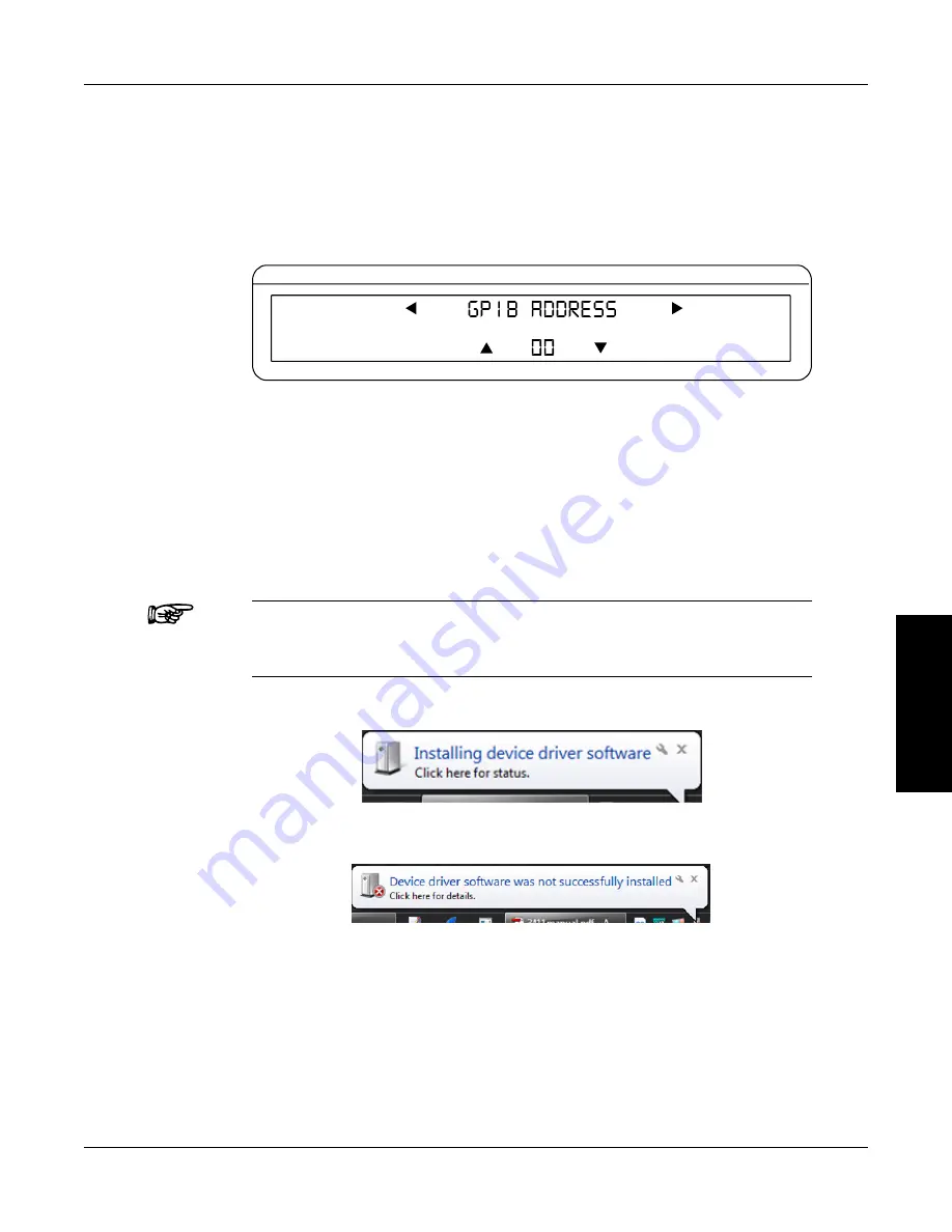
buttons until GPIb ADDRESS is reached. The display should appear as
follows:
CURRENT
VOLTAGE
POWER/PF
Figure 5–2 GPIB Address Setup Menu
5. Use the
p
and
q
buttons until desired primary address is reached (range 0-15).
6. Press ENTER to return to main menu.
5.2
usb driver setup for WindoWs operation system
Copy the 7500.drivers.msi from the Magtrol Manual CD at programs\7500 Drivers directory into
local drive of your PC.
NOTE:
If your PC is 64 bit operation system, then you need 7500Vx.inf to
setup USb driver. If your PC is 32 bit operation system, then you
need 7500Vx.xp.inf to setup USb driver.
1. Power on the 7500. A window in the right corner will show “Installing device driver software”.
2. Click on the balloon depicted below will show which drivers did not install successfully.
3. The 7500 is a composite device meaning that it offers more than one USb interface to your
PC. The first device is a communications device class, also known as a virtual COM port.
This interface allows the USb to act as a legacy RS-232 device, and allows you to use
programs such as hyperterminal to control the 7500. The second interface is a USb Test and
Measurement device. Drivers for this interface may already be installed on your computer.
They are included as part of the MTEST 7 software. LabVIEW installations also include a
version of compatible drivers to use with a test and measurement class interface. If you have
either of these programs installed on your computer, when you click on the aforementioned
balloon, the following window will appear.


