background image

ASSEMBLY INSTRUCTIONS
MAGNUM INDUSTRIAL MI-91520 DELUXE 14” BAND SAW

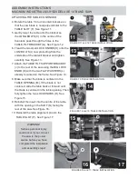
INSTALLING THE FENCE ASSEMBLY
The MI-91520 is equipped with a deluxe T-fence 
and  guide  rail  system. Follow all  assembly  and 
adjustment instructions
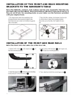
INSTALLATION  OF  THE  FRONT AND  REAR 
MOUNTING BRACKETS TO THE  BANDSAW’S 
TABLE on page 18~23
INSTALLING THE FENCE ASSEMBLY
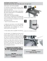
This band saw is equipped with a foot brake locat-
ed at the bottom of the machine. The foot brake 
allows for  immediate immobilization of the blade 

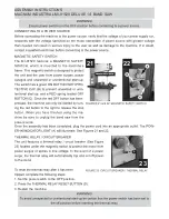
1. Open the lower wheel cover door.

2. Attach  the  foot  brake  to  the  FOOT  BRAKE 
MOUNTING BAR (Q) using the two supplied CAP 
SCREWS AND LOCK WASHERS (R), in the as-
sembly order shown in Figure 20.

3. Firmly tighten with the supplied 8 mm Allen key.

The foot brake is not designed to function as the 
primary  stop  mechanism  of  this  saw. The  foot 
brake should be used for emergency situations or 
any time it is necessary  to immobilize the blade 
quicker than normal. Under normal working condi-
tions the red stop button  should be used as  the 
primary stop mechanism. Continuously using the 
foot  brake  as  the  primary  stop  mechanism  can 
lead  to  premature  wear  of  the  brake  and  may 
cause damage to the motor.

WARNING!

This tool is for indoor use only. Do not 

expose to rain or use in wet or damp 

locations.

EMERGENCY FOOT PEDAL STOP 

MAY NEED TO BE ADJUSTED MACHINE  

WILL NOT START IF THE LIMIT SWITCH 

IS ACTIVATED

WARNING!

Do not operate the unit with a damaged 

power cord or plug.

18

19

20

FIGURE 18: FENCE INSTALLATION

FIGURE 19: FOOT BRAKE LOCATION

FIGURE 20: FOOT BRAKE INSTALLATION

Summary of Contents for MI-91520

Page 1: ...OPERATING MANUAL MODEL NO MI 91520...

Page 2: ...s and Equipment disclaims any real or implied warranty and holds itself harmless for any injury that may result from the improper use of its equipment chinery with locks master electrical switches and...

Page 3: ...Blade Width 3 4 Minimum Blade Width 1 8 Floor to Table Height 36 1 2 Cutting Capacity Throat 13 1 2 Maximum Width of Cut 13 1 2 Maximum Depth of Cut 12 Ideal for Ripping Dust Collection Ports 2 Ports...

Page 4: ...GAUGE G TABLE ALIGNMENT PIN H FENCE FRONT RAIL I LOWER WHEEL COVER DOOR LOCK KNOB J FOOT BRAKE FIGURE 1 FRONT VIEW FIGURE 2 REAR VIEW K MAGNETIC SAFETY SWITCH L BLADE TRACKING ADJUSTMENT KNOB M BLADE...

Page 5: ...ASSEMBLY INSTRUCTIONS MAGNUM INDUSTRIAL MI 91520 DELUXE 14 BAND SAW FIGURE 3 CONTENTS w T LIST OF CONTENTS I A TABLE T T WARNIN ADDITIONAL REQUIREMENTS FOR SET 3 B C D E F I G...

Page 6: ...ASSEMBLY INSTRUCTIONS MAGNUM INDUSTRIAL MI 91520 DELUXE 14 BAND SAW tor Mark out the safety zone with nonslip paint or tape Take steps to ensure that all operators and 4...

Page 7: ...to 45 to the right These adjustments are easy to make with the angle scale and lock knobs 1 Remove the RED INSERT A from the centre of the table and the TABLE ALIGNMENT PIN B from the table slot See F...

Page 8: ...KNOB K with the two FLAT WASHERS L already mounted on the frame See Figure 14 8 Make sure that the blade is centered in the TABLE OPENING M If the blade is not centered slide the table back or forwar...

Page 9: ...3 Firmly tighten with the supplied 8 mm Allen key The foot brake is not designed to function as the primary stop mechanism of this saw The foot brake should be used for emergency situations or any tim...

Page 10: ...ONS MAGNUM INDUSTRIAL MI 91520 DELUXE 14 BAND SAW CONNECTING TO A POWER SOURCE The MI 91520 features a MAGNETIC SAFETY power source to the motor 1 Set the power switch to the OFF position 3 Restart th...

Page 11: ...TOR A ADJUSTING 90 TABLE STOP AND RE ALIGNING ANGLE POINTER 1 Loosen LOCK KNOBS C and LOCK KNOB B 5 Loosen the LOCK KNOBS B AND C and make sure the FIGURE 24 TABLE TILT ADJUSTMENT FIGURE 25 TABLE TILT...

Page 12: ...BASIC ADJUSTMENTS MAGNUM INDUSTRIAL MI 91520 DELUXE 14 BAND SAW other FIGURE 36 SPEED ADJUSTMENT FIGURES 39 and 40 SPEED ADJUSTMENT 36 37 38 39 40...

Page 13: ...ng out of position during cutting and to reduce risks of injuries expose a minimum amount of blade The blade guard should be set 1 8 to 1 4 above the work To adjust the height of the blade guard is di...

Page 14: ...any all purpose grease The motor and all bearings are sealed and permanently lu bricated They require no further lubrication No other part of this band saw needs lubrication PERIODIC MAINTENANCE not...

Page 15: ...91520 DELUXE 14 BAND SAW 5 Determine how many shim washers you need to compensate for the distance measured in Step 3 and place them on the wheel shaft To adjust the lower wheel do these steps to make...

Page 16: ...INSTALLATION OF THE FRONT AND REAR RAILS Note The M6 bolts washers lock washers and hex nuts required for this step are provided with your Excalibur Universal Bandsaw Rip Fence System However if with...

Page 17: ...INSTALLATION OF THE FENCE...

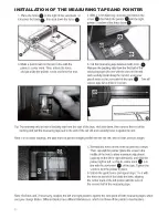
Page 18: ...INSTALLATION OF THE MEASURING TAPE AND POINTER...

Page 19: ...INSTALLATION OF THE RESAW GUIDE...

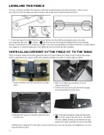
Page 20: ...LEVELING THE FENCE VERTICAL ADJUSTMENT OF THE FENCE 90 TO THE TABLE...

Page 21: ...ALIGNMENT OF THE FENCE PARALLEL TO THE MITER SLOT...

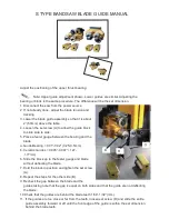
Page 22: ...between the bearing and the blade a Guide Bearing 0 01 0 02 0 25 0 5mm b Ceramic Guides 0 005 0 007 127 177mm 6 Slide the block up to the feeler gauge and blade without deflecting the blade 7 Hold the...

Page 23: ...ring side shield material 3 Hold the block in position and tighten the set screw E 4 Loosen the set screw G and slide the bearing shaft forward or aft as needed until the edge of the bearing just touc...

Page 24: ......

Page 25: ......

Page 26: ...101 104 114 103 120 115 101 102 119 118 117 116 115 130 102 131 132 133 138 121 103 101 139 133 141A 5 141A 4 141A 1 141A 2 141A 3 141A 6 142 143 144 145 146 147 148 149 151 150 152 166 167 160 159 15...

Page 27: ......

Page 28: ......

Page 29: ......

Page 30: ......

Page 31: ...LL BEARINGS KIT CERAMIC KIT S4 S13 S23 S12 S10 S44 S5 S43 S6 S7 S8 S7 S21 S20 S19 S18 S43 S17 S7 S7 S5 S21 S8 S6 S4 S43 S9 S43 S1 S2 S43 S3 S17 S43 S18 S19 S20 S4 S15 S43 S4 S15 S16 S43 S4 S15 S43 S4...

Page 32: ......

Page 33: ...PARTS LISTS FOR RS FENCE...

Page 34: ......

Page 35: ...MITER GAUGE FENCE JIG...

Reviews: