Thrust Bearing Adjustment
Note: Upper thrust bearing shown. Lower thrust bearing is similar.
1. Loosen the set screw (E) (hidden) to allow the
thrust bearing block to slide side to side.
2. Slide the block to position the outer bearing cage
just past the edge of the blade (F). You will just
barely see the edge of the bearing side shield
material.
3. Hold the block in position and tighten the set screw
(E).
4. Loosen the set screw (G) and slide the bearing
shaft forward or aft as needed until the edge of the
bearing just touches the spine of the blade without
deflecting the blade.
5. Hold the shaft in position and tighten the set screw
(G).
6. Adjust the lower thrust bearing using the same steps.
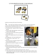
1. Change the lower S guide on 14'' bandsaw
a. Put and fasten the plate on the base first.
b. Put and fasten the S blade guide on the plate.
E
F
G
D
Summary of Contents for MI-91520
Page 1: ...OPERATING MANUAL MODEL NO MI 91520...
Page 17: ...INSTALLATION OF THE FENCE...
Page 18: ...INSTALLATION OF THE MEASURING TAPE AND POINTER...
Page 19: ...INSTALLATION OF THE RESAW GUIDE...
Page 20: ...LEVELING THE FENCE VERTICAL ADJUSTMENT OF THE FENCE 90 TO THE TABLE...
Page 21: ...ALIGNMENT OF THE FENCE PARALLEL TO THE MITER SLOT...
Page 24: ......
Page 25: ......
Page 27: ......
Page 28: ......
Page 29: ......
Page 30: ......
Page 32: ......
Page 33: ...PARTS LISTS FOR RS FENCE...
Page 34: ......
Page 35: ...MITER GAUGE FENCE JIG...

