S TYPE BANDSAW BLADE GUIDE MANUAL
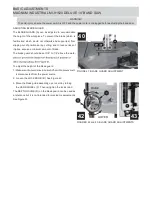
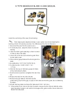
Adjust the positioning of the upper thrust bearing:
Note: Upper guide adjustment shown. Lower guides are similar. Adjusting the
bearing or block is the same procedure. The difference will be the set dimension.
1. Disconnect the saw from the power source.
2. If not already done, adjust the blade tension and
tracking.
3. Lower the blade guide assembly so that it is about
2” (50mm) above the table.
4. Loosen the set screw (A) to allow the guide block
to slide side to side.
5. Place a feeler gauge between the bearing and the
blade.
a. Guide Bearing = 0.01”-0.02" (0.25-0.5mm)
b. Ceramic Guides = 0.005”-0.007” (.127-
.177mm)
6. Slide the block up to the feeler gauge and blade
without deflecting the blade.
7. Hold the block in position and tighten the set screw
(A).
8. Repeat the steps for the other side (B).
9. Recheck the gap between the blade and the
guides taking note that the gap is equal on both sides and that the guide are not deflecting
the blade.
10.Check that the guides are behind the blade teeth 1/64”-1/32” (mm).
11. If the guides are too close or far from the teeth, loosen set screw (D) and slide the entire
guide assembly forward or aft until the front edge of the guide is within the set dimension
behind the blade teeth.
B
O
R
Summary of Contents for MI-91520
Page 1: ...OPERATING MANUAL MODEL NO MI 91520...
Page 17: ...INSTALLATION OF THE FENCE...
Page 18: ...INSTALLATION OF THE MEASURING TAPE AND POINTER...
Page 19: ...INSTALLATION OF THE RESAW GUIDE...
Page 20: ...LEVELING THE FENCE VERTICAL ADJUSTMENT OF THE FENCE 90 TO THE TABLE...
Page 21: ...ALIGNMENT OF THE FENCE PARALLEL TO THE MITER SLOT...
Page 24: ......
Page 25: ......
Page 27: ......
Page 28: ......
Page 29: ......
Page 30: ......
Page 32: ......
Page 33: ...PARTS LISTS FOR RS FENCE...
Page 34: ......
Page 35: ...MITER GAUGE FENCE JIG...

