background image

13 

© 2010 Magnum Energy, Inc.

2.0 Installation

2.6 Warning Label

It might be falsely assumed that it is safe to perform maintenance on the 

generator or the electrical panel because the generator is off; however, the 

AGS system can automatically turn on the generator and power the panel.
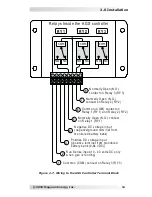
Two warning labels as shown in Figure 2-8 are provided to inform all personnel 

that an Automatic Generator Starting device is installed in your electrical 

system. Place one label in a clearly visible location at the generator and the 

other label at the electrical panel that is being powered by the generator.

WARNING: To prevent harm to servicing personnel, e

nsure the gen-

erator and AGS are properly disabled (i.e., remove the starting battery 

from the generator and remove all power to the AGS by u

nplugging 

the green 8-port friction-fi t terminal block from the controller

) prior 

to performing maintenance on the generator or electrical panel.

2.7 Common ME-AGS-S Generator Wiring Diagrams

The most common generator starting/run/stop circuits can be divided into 

three major types - Two-wire, Three-wire “momentary”, or Three-wire “main-

tain”. The following generator wiring diagrams are provided to give examples 

of these generator types.

Info: The term “Three-wire” refers to the minimum number of wires 

required to control the starter motor and run the generator; more  

than three wires may actually be needed.

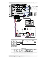
Shown in Figure 2-9, the “Two-wire” generator types integrate the control 

circuits for start-up, running and stopping. The generator starts and runs when 

two “control” wires are connected and stops when they are disconnected.
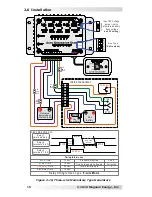
Shown in Figure 2-10, the “Three-wire momentary” generator types use a 

three-position momentary type switch that controls their operation. To start 

the generator, the switch is momentarily held to the START position. This 

energizes the ignition system and cranks the starter motor. Once the engine 

has started, the START switch is released and it returns to a center position 

(i.e., “momentary” run control). To shut down the generator, the switch is 

held to the STOP position until the engine dies. Once the switch is released, 

it returns to the center position (i.e., “momentary” stop control).
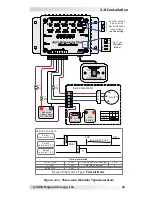
Shown in Figure 2-11, the “Three-wire maintain” generator types use an au-

tomotive type starting circuit. Operating a switch that is fi rst turned to a RUN 

position and then momentarily held to a START position to start the generator. 

Once the engine has started, the switch is released and it returns to the RUN  

position (i.e., “maintain” run control). To shut down the generator, the switch 

is moved to the OFF position (i.e., “maintain” stop control).

Figure 2-8, 

Warning Label

T h is electrical system is eq u ip p ed  with  an  A u to matic 
Gen erato r Startin g  (A GS) d evice an d/o r an  in verter. 
D isco n n ect all A C  an d  D C  p o wer to  th e A GS an d/o r 
in verter b efo re p erfo rmin g  an y service to  th e electrical 
system. F ailu re to  d o  so  can  resu lt in  sh o ck cau sin g  
serio u s  in ju ry  o r  d eath.

PN : 62 -0002  R ev A

W A R N IN G

This electrical system is equipped with an Automatic 
Generator Starting (AGS) device and/or an inverter. 
Disconnect all AC and DC power to the AGS and/or 
inverter before performing any service to the electrical 
system. Failure to do so can result in shock causing 
serious injury or death.                          

PN: 62-0002 Rev A

Summary of Contents for ME-AGS-S

Page 1: ...Owner s Manual ME AGS S Automatic Generator Start For Standalone Systems ...

Page 2: ...permission by Magnum Energy Inc Safety Symbols To reduce the risk of electrical shock fire or other safety hazard the fol lowing safety symbols have been placed throughout this manual to indicate dangerous and important safety instructions WARNING This symbol indicates that failure to take a specified ac tion could result in physical harm to the user CAUTION This symbol indicates that failure to t...

Page 3: ...le 3 2 ME AGS S Default Settings 19 Table 6 1 Troubleshooting Guide 25 List of Figures Figure 1 1 ME AGS S Remote Switch Features 2 Figure 1 2 ME AGS S Communications Cable 2 Figure 1 3 ME AGS S Controller Features 3 Figure 2 1 ME AGS S System Diagram 5 Figure 2 2 Controller Dimensions 7 Figure 2 3 Remote Dimensions 7 Figure 2 4 Communication Cable Connection 8 Figure 2 5 Communication Cable Data ...

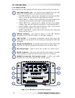
Page 4: ... more worrying about dead batteries The AGS System includes a controller with on board adjustments and inter faces with a user friendly remote control switch The controller provides the wiring interface for the battery bank and generator start stop circuits It has adjustments for setting the generator s run time high temperature start and low battery voltage start and if needed the Clock and Quiet...

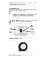
Page 5: ...ine when to automatically start the generator OFF disables the AGS generator start stop functions TEST initiates an automatic generator start stop sequence for testing generator wiring and operation 2 STATUS Indicator this bi color green or red LED indicator illuminates to provide information on the AGS operation 3 Temperature Sensor internal location of the internal sensor used to start the gener...

Page 6: ... feature to function correctly QUIET TIME PM AM used to prevent the generator from starting during specific hours 2 STATUS Indicator this bi color green or red LED indicator illuminates to provide information on the AGS operation 3 TEST Switch a momentary pushbutton switch that allows the AGS system to be tested for correct wiring and generator start stop operation 4 Wiring Terminal Block this 8 p...

Page 7: ...nt generator damage and obtain reliable operation use generator models designed for unattended operation These models should also be equipped with remote operation connections and have protective systems that cause the generator to shut down from low oil pressure over tem perature starter lockout and over crank conditions The ME AGS S controller is connected to the switch by a 25 communica tions c...

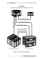
Page 8: ... version M onitored Battery Bank Auto Start Generator Generator start stop w iring Generator run signal B atter y v oltage R em ote connection C om m on battery negatives M onitored battery and Generator starting battery Figure 2 1 ME AGS S System Diagram 2 0 Installation ...

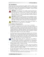
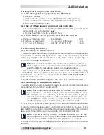
Page 9: ...it connector from the controller by pulling it straight out Wait to plug this 8 pin connector back into the AGS controller until after the installation is completed and the AGS Functional Tests are performed in Section 3 3 3 Mount the AGS controller using the four 8 x 3 4 screws provided 2 3 2 Mounting the AGS Remote Switch 1 Select a location that is convenient clean dry and protected from extrem...

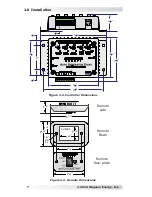
Page 10: ...Figure 2 2 Controller Dimensions 9 16 3 7 8 4 3 16 2 1 16 4 3 8 3 8 5 1 4 3 7 16 2 5 16 1 3 16 cutout bezel face plate switch side 7 64 drill bit 5 16 2 1 4 1 3 16 1 5 8 1 7 16 3 1 8 1 1 8 2 3 4 2 Remote side Remote Bezel Remote face plate 2 0 Installation ...

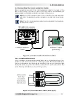
Page 11: ...e extended to a maximum of 250 feet if needed ME AGS S Controller Remote Switch backside Communications Cable Figure 2 4 Communication Cable Connection Figure 2 5 Communication Cable Data Type 1 2 3 4 5 6 1 2 3 4 5 6 w hite blue TAB TAB same colors from top to bottom tabs facing toward you 2 4 1 Communication Cable The 6 conductor communications cable has a RJ12 6 position 6 wire con nector on eac...

Page 12: ...k 2 5 2 Generator Run Sense Connection Terminal 2 Terminal 2 on the 8 port terminal block is used as a generator run sense i e switched B or a positive battery signal from the hour meter or gen running light This run sense voltage is used to determine that the genera tor is running and to prevent another starter crank while the generator is already running Info The run sense signal from the genera...

Page 13: ... charge power equipment batteries and plug into the generator s 120VAC output The step down transformer provides 12 VDC output only while the generator is running negative D C F use 5 A m ax run s ens e AGS T erm inal Block Ports 1 2 3 4 5 6 7 8 On Generator 120VAC Outlet 120 VAC IN 12 VD C OU T TR AN SFOR M ER What if my generator does not have a run sense output If your gen erator is not equippe...

Page 14: ... relays Fuses should be located as close as possible to the genera tor connection A fuse must be used even if the circuit is providing only a dry contact or ground connection it will prevent damage if the connection is miswired or damaged Info To set the generator type which determines the operation of the AGS relays see GEN TYPE Setting in the Setup section Info Due to the different generator typ...

Page 15: ...VD C N egative D C voltage input negative ground terminal from monitored battery bank R un Sense input 10 40 volts D C only w hen gen is running C ommon C OM contact on R elay 3 R Y3 N ormally Open N O contact on R elay 3 R Y3 C ommon C OM contact on R elay 1 R Y1 and R elay 2 R Y2 N ormally Open N O contact on R elay 2 R Y2 N ormally Open N O contact on R elay 1 R Y1 8 7 1 2 3 4 5 6 R Y2 R Y3 R e...

Page 16: ...s when two control wires are connected and stops when they are disconnected Shown in Figure 2 10 the Three wire momentary generator types use a three position momentary type switch that controls their operation To start the generator the switch is momentarily held to the START position This energizes the ignition system and cranks the starter motor Once the engine has started the START switch is r...

Page 17: ...er set to M onitored battery bank voltage on 24 V setting Gen Hour Meter 0 1 2 3 GEN AN D POWER I O R 2 R elay 1 terminals 5 6 D ela y R elay 2 terminals 6 7 R U N TIM E H OU R S R U N OFF R elay timing for Gen Type 2 W ire Maintain Mode R 2 R elay 2 Time D elay time Time betw een start attempts 10 sec 4 sec 2 min Tim ing Inform ation Total Start attempts 4 R elay 3 terminals 1 8 OFF IN S I D E IN...

Page 18: ... PR EH EA T STA R T STOP 5 am p fuse GEN AN D POWER I O R elay 1 terminals 5 6 R elay 2 terminals 6 7 R elay timing for Gen Type 5 wire Mode STOP Time START Time Time betw een start attempts 10 sec 10 sec 4 sec Tim ing Inform ation Total Start attempts 2 minutes PR EH EA T Time 25 sec R elay 3 terminals 1 8 Start Delay D e la y R U N TIM E H OU R S PR EH EA T START STOP STOP 4 Preheat D elay time ...

Page 19: ...inals 6 7 R elay timing for Gen Type Portable Mode STAR T Time T1 Time Time betw een start attempts 10 sec 5 sec 2 min Tim ing Inform ation Total Start attempts 4 D elay time 2 sec R elay 3 terminals 1 8 T1 OFF R U N TIME H OU R S R U N Delay START D elay 5 am p fuse Input D C Voltage jumper set to Monitored battery bank voltage on 24V setting Monitored battery bank 12V 24V 48V I N S I DE INS IDE ...

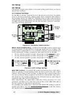
Page 20: ...ver to access an input DC voltage jumper and a 4 position DIP Dual In line Package switch The INPUT DC VOLTAGE jumper position determines the controller s DC operating voltage The DIP switch configuration is used to select the GEN TYPE which determines how the internal relays operate to automati cally start and stop generators Figure 3 2 DC Voltage Settings GEN TYPE Setting The GEN TYPE setting is...

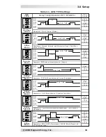
Page 21: ... w ith rem ote control H onda Generators R M Y Series Kohler D ynaGen C ontrollers Generator PT EC U 63 controller w ith 2 w ires Pow ertech O N 4 3 2 1 ON 4 3 2 1 ON 4 3 2 1 T2 10 sec R Y3 N O R Y3 N O ON 4 3 2 1 R Y1 N O R Y2 N O T 1 R U N TIM E T 3 T 2 T3 R Y3 N O R Y1 N O R Y2 N O T 2 T 1 T 1 R U N TIM E R Y1 N O R Y3 N O R Y2 N O T3 5 sec T3 R Y2 N O R Y3 N O T 1 T 2 R U N TIM E T1 4 sec T2 1...

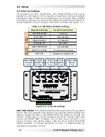
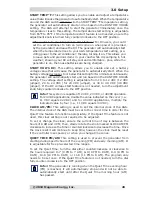
Page 22: ...ator will run after the generator has started The generator starts because the battery voltage has fallen to the START VOLTS DC setting for at least two minutes continuously or the temperature around the remote switch has risen to the START TEMP F setting The run time can be set from 1 to 5 hours To change this setting slowly rotate the knob marked RUN TIME HOURS clockwise to increase generator ru...

Page 23: ...DC for 24 VDC jumper or 40 to 48 VDC 48 VDC jumper If the DC voltage start feature is not needed turn the adjustment knob fully counterclockwise to the OFF position Info This system is capable of 12 VDC 24 VDC or 48VDC operation For 24 VDC applications double the value indicated on the cover i e 11 VDC equals 22 VDC and for 48 VDC applications multiply the indicated value by four i e 11 VDC equals...

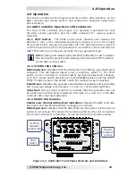
Page 24: ... Test This start stop test is used to confirm that all wiring from the generator to the AGS controller is correct and that the GEN TYPE setting is configured correctly for your generator type 1 Press and release either a the red TEST switch on the Controller see Figure 4 1 or b the switch to the TEST position on the Remote Switch see Figure 4 2 2 After the TEST button switch is pressed and release...

Page 25: ...ing Green Indicates that the AGS system is initiating a generator start sequence This can happen based on two conditions either 1 The TEST switch on the controller or remote switch has been pressed and released or 2 The remote switch has been set to the ENABLE position and the START TEMP F setting and or the START VOLTS DC setting has been reached Solid Green Indicates the generator has started su...

Page 26: ... automatic generator start stop sequence This test will attempt to turn on the connected generator and allow it to run for at least 30 seconds before turning the generator off This start stop test is used to confirm that all wiring from the generator to the AGS is correct and that the AGS is configured correctly for your generator type Info Pushing and releasing the momentary TEST position enables...

Page 27: ...ntil the RUN TIME HOURS setting is reached at which time a stop signal will be sent to the generator If the generator is running when the switch is pushed to the TEST posi tion the generator will stop and then start again The generator will then run for approximately 30 seconds before shutting off There is a two minute delay before the AGS attempts to start the generator if the voltage to the AGS ...

Page 28: ... green 8 port friction fit terminal block from the AGS controller before servicing the electrical or gen erator system to prevent harm to servicing personnel LED Indication Symptom Solution STATUS is ON red Gen Fault 1 Gen won t start or 2 Gen won t run It starts but is stopped by the AGS B or run sense voltage not sensed to terminal 2 Check Gen to AGS start wiring or check B wiring from GEN to AG...

Page 29: ...e product for repair determined by the price paid by the original purchaser Magnum Energy shall not be liable for any other losses or damages 4 Upon request from Magnum Energy the original purchaser must prove the product s original date of purchase by a dated bill of sale itemized receipt 5 The original purchaser shall return the product prepaid to Magnum Energy in Everett WA After the completion...

Page 30: ...y com If returning your Product directly to Magnum Energy for repair you must Return the unit in the original or equivalent shipping container Receive a Return Materials Authorization RMA number from the factory prior to the return of the Product to Magnum Energy for repair Place RMA numbers clearly on the shipping container or on the packing slip When sending your Product for service please ensur...

Page 31: ... inverter applications The MMP Series en closures combine all of the major components required for a renewable energy system inverter battery disconnect AC overcurrent protection grounding connections and a full system inverter bypass into a single easy to install pre wired enclosure Advanced Remote Control Display The ME ARC allows advanced features of the Magnum inverter or accessory to be confi...

Page 32: ...PN 64 0004 Rev A Magnum Energy Inc 2211 West Casino Rd Everett WA 98204 Phone 425 353 8833 Fax 425 353 8390 Web www magnumenergy com ...

Reviews: