© 2010 Magnum Energy, Inc.
2
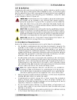
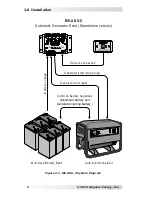
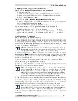
1.1 ME-AGS-S Components/Features
The ME-AGS-S is equipped with the following components and features:
• AGS Remote Switch • Communications Cable • AGS-S Controller
1.1.1 AGS Remote Switch
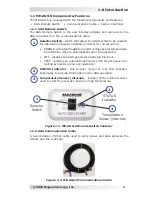
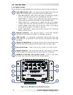
The AGS Remote Switch is the user interface display and connects to the
AGS controller thru the communications cable.
1
Selector Switch - switch that allows the AGS system to be enabled
for automatic generator operation and test for correct wiring.
ENABLE - activates the AGS to monitor voltage and/or temperature
to determine when to automatically start the generator.
OFF - disables the AGS generator start/stop functions.
TEST - initiates an automatic generator start/stop sequence for
testing generator wiring and operation.
•
•
•
2
STATUS Indicator - this bi-color (green or red) LED indicator
illuminates to provide information on the AGS operation.
3
Temperature Sensor (internal) - location of the internal sensor
used to start the generator based on high temperature.
1.1.2 AGS Communication Cable
A six-conductor, 25-foot cable used to carry power and data between the
remote and the controller.
Figure 1-2, ME-AGS-S Communications Cable
1.0 Introduction
Figure 1-1, ME-AGS-S Remote Switch Features
2
STATUS
Indicator
3
Temperature
Sensor (internal)
1
Selector
Switch


