background image

© 2016 Sensata Technologies


6

Installation

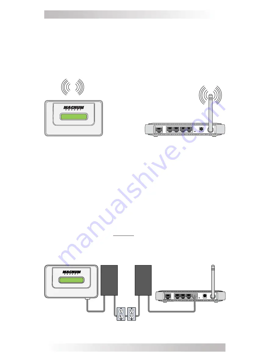
Figure 8, Connecting the MagWeb GT Wirelessly

2.4.3  Connecting using a PLC Bridge

Note: A PLC bridge uses the power line to communicate, and requires 

both a “send” and “receive” unit (see Figure 9). The quality and 

length of the CAT5 network cable will affect the quality of the MagWeb 

GT’s communication. You can use a Switch to enhance quality of 

communication, if necessary. 

1.  Ensure the CAT5 network cable is connected to the Network port 

on the bottom of the MagWeb GT.

2.  Connect the other end of the CAT5 network cable to the “send” 

unit of the PLC bridge.

3.  Route and connect another CAT5 network cable from the 

“receive” unit of the PLC bridge to an open port on the broadband 

router (refer to your bridge user’s manual for specifi c operating 

instructions).

Figure 9, Connecting the MagWeb GT to a PLC Bridge

SEND

RECEIVE

2.4.2 Connecting 

Wirelessly

Refer to Section 5.1.2,  “Connecting to the MagWeb GT Wirelessly” 

for information on this procedure.
In WLAN mode, the MagWeb GT can connect to a wireless broadband 

router via Wi-Fi to access the local web (Figure 8). In Local Wireless 

Access mode, you can use your phone or a PC (requires a network 

cable) to connect to the MagWeb GT and access the local web.

Summary of Contents for MagWeb GT

Page 1: ...Owner s Manual MagWeb GT ...

Page 2: ...fe support system or to affect the safety or effectiveness of that system If the MagWeb GT fails it is reasonable to assume the health of the user or other persons may be endangered Copyright Notice Copyright 2016 by Sensata Technologies All rights reserved Permission to copy distribute and or modify this document is prohibited without written permission from Sensata Document Information Descripti...

Page 3: ...g the MagWeb GT 13 5 1 Connecting to the MagWeb GT via LAN 13 5 2 Connecting Directly to MagWeb GT via Ethernet 13 5 3 Connecting Directly to MagWeb GT Wirelessly 14 5 3 1 Viewing the MagWeb GT s Home Screen 14 5 4 Using the Micro GT Status Screens 15 5 4 1 Viewing Real Time Data 15 5 4 2 Viewing System Power Trends 15 5 4 3 Viewing Energy Generation Statistics 16 5 5 Using the Battery System Stat...

Page 4: ...igure 15 Wireless Connection Operating Interface 10 Figure 16 MagWeb GT Menu Button 11 Figure 17 MagWeb GT Menu Structure 11 Figure 18 MagWeb GT Signal Level Screen 11 Figure 19 MagWeb GT Status Screen 12 Figure 20 MagWeb GT Shutdown Screen 12 Figure 21 MagWeb GT Home Screen 14 Figure 22 Real Time Data Screen 15 Figure 23 System Power Trend Screen 15 Figure 24 Power Generation Statistics Screens 1...

Page 5: ...ral electrical codes Before installing or using the MagWeb GT please read all instructions and cautionary markings in the technical documents Use insulated tools to reduce the chance of electrical shock or accidental short circuits Make sure to use a dedicated outlet for the MagWeb GT Do NOT plug any other devices into the same outlet as the MagWeb GT Do NOT plug the MagWeb GT into a power strip s...

Page 6: ...ter performance even if the MagWeb GT fails to communicate with the inverters The MagWeb GT is NOT a revenue grade metering device Power production data collected by the MagWeb GT is for reference only Check your utility meter for the real power production of the whole system 1 1 System Features Collects individual module and microinverter statistics Communicates in real time Requires no additiona...

Page 7: ...o your local network via a CAT5 cable This port can be used as a direct connection to the network router or as an indirect connection that goes through a Wi Fi extender or PLC bridge USB Port The USB port can be used as a power source 5VDC for a Wi Fi bridge if necessary It is NOT a two way communication port and is therefore incompatible with external Wi Fi devices such as Wi Fi dongles or thumb ...

Page 8: ...on that is located as electrically close to the solar sub panel as possible on a dedicated circuit this enhances the Power Line Communications PLC signal Note Locating the MagWeb GT at or very near the solar sub panel may not be the most convenient location but it ensures a clean PLC signal and a stable data stream The MagWeb GT is NOT rated for outdoor use so if installing outdoors near a junctio...

Page 9: ...ting the MagWeb GT use either two 8 drywall screws or two wall anchors installed 5 1 130 mm apart The drywall screws and wall anchors are NOT supplied with the MagWeb GT 2 Align slide the MagWeb GT onto mounting screws Figure 5 Best Practice Install connect the MagWeb GT to the Internet while the rest of the array is being installed Doing so allows the MagWeb GT to automatically update its interna...

Page 10: ...Initial Connection to the Internet There are three ways to initially connect the MagWeb to the Internet A direct CAT5 cable connection to a broadband router A wireless connection to a broadband router Using a PLC bridge to connect to a broadband router 2 4 1 Connecting Directly using a CAT5 Cable 1 Ensure the CAT5 network cable is connected to the Network port on the bottom of the MagWeb GT 2 Conn...

Page 11: ...t the other end of the CAT5 network cable to the send unit of the PLC bridge 3 Route and connect another CAT5 network cable from the receive unit of the PLC bridge to an open port on the broadband router refer to your bridge user s manual for specific operating instructions Figure 9 Connecting the MagWeb GT to a PLC Bridge SEND RECEIVE 2 4 2 Connecting Wirelessly Refer to Section 5 1 2 Connecting ...

Page 12: ...ed standard AC electrical outlet WARNING Make sure to use a dedicated outlet for the MagWeb GT Do NOT plug any other devices into the same outlet as the MagWeb GT WARNING Do NOT plug the MagWeb GT into a power strip surge protector GFIC receptacle AFCI breakers or an uninterruptable power supply UPS The surge suppression and or filtering on these types of devices will substantially diminish PLC pe...

Page 13: ...ng Software Wireless IP Address 2 Awaiting the entering of inverter IDs Figure 11 Figure 12 The first time see note at top of next page the MagWeb GT is powered up it displays the available internal LAN IP address as well as the Wireless network IP address See Managing the Network Connection on page 19 if you need to access the MagWeb GT through the Local Area Network LAN Figure 12 Input Inverter ...

Page 14: ...agWeb Internet Communication L 192 168 1 101 W 750W 11 45Kwh 06 Setup LAN IP Address The LCD display on the front of the MagWeb GT shows an IP address Example 192 168 1 101 if the connection to the router is successful IP addresses vary check with the router s user manual for specifics However if the LCD displays 192 168 131 228 the MagWeb router connection has not been successful In that case che...

Page 15: ... microinverters does not match the number of IDs programmed into the MagWeb GT see Managing Inverter IDs page 19 Note The MicroGT IDs must be programmed into the MagWeb GT for it to recognize the microinverters The MagWeb GT will NOT automatically sense the microinverters see Managing Inverter IDs If connected via Wi Fi Figure 15 Wireless Connection Operating Interface Wireless IP Address W 192 16...

Page 16: ...7 MagWeb GT Menu Structure Press and hold the MENU button to cycle thru the menus Release the button to gain access to the functionality of each menu item Exit Menu Press to return the MagWeb GT to the normal operating screen see Figure 14 or 15 Signal Level The communication strength between microinverters and the MagWeb GT is measured from 1 5 A higher number of symbols indicates a stronger sign...

Page 17: ...verters will be turned off Choose Cancel and the MagWeb GT will exit the menu Note Leaving the MENU button untouched for one minute returns the MagWeb GT to the main menu Figure 17 Figure 19 MagWeb GT Status Screen Figure 20 MagWeb GT Shutdown Screen Connected 05 Total 06 OK Cancel 4 2 Resetting MagWeb GT to its Factory Defaults Insert a paperclip or something similar into the Reset slot on the bo...

Page 18: ...select Network and Sharing Center 4 Select Local Area Connection for the Unidentified Network 5 Press Properties 6 Highlight Internet Protocol Version 4 TCP IPv4 7 Press Properties 8 Select the Use the Following IP Address radial button and then enter the IP Address and Subnet Mask as listed below Do not enter anything in the DNS Server address section IP Address 192 168 131 1 Subnet Mask 255 255 ...

Page 19: ...ome Home Micro GT Status Battery System Status Administration ENERGY COMMUNICATION UNIT ECU ID Lifetime Generation Last System Power Generation of Current Day 204000000322 2 978 61 kWh 3 301 W 33 30 kWh Last Connection to Website Number of Inverters Last Number of Inverters Online Current Software Version 2016 09 01 10 41 20 6 4 V4 0NA Current Time Zone ECU Eth0 Mac Address ECU Wlan0 Mac Address I...

Page 20: ... select the Micro GT Status tab The Real Time Data screen appears Figure 22 Figure 22 Real Time Data Screen 5 4 2 Viewing System Power Trends From the Micro GT Status tab click Power from the list at right The Power screen appears Figure 23 Figure 23 System Power Trend Screen Administration ID Management Real Time Data Home Micro GT Status Battery System Status Administration Inverter ID 403000146...

Page 21: ... Power Generation Statistics 2016 09 02 Query Current Week 10 08 26 08 27 08 28 08 29 08 30 09 01 09 02 Solar Generated Current Week 35 86 KWH ID Management Energy kWh Real Time Data Power Energy 8 6 4 2 0 Power Generation Statistics 2016 09 01 Query Current Month Solar Generated Current Month 43 26 KWH 10 Energy ID Management Energy Energy kWh Real Time Data Power Energy 30 20 10 0 Power Generati...

Page 22: ...Fault DC Volts 54 9 VDC DC Amps AC Volts Hz Output AC Input Volts Battery Temp 11 4 Amps DC 119 VAC 60 1 Hz 185 VAC 12 C 53 6 F Transformer Temp FET Temp 39 C 102 2 F 36 C 96 8 F Battery Monitor Inverter MS4448PAE State of Charge DC Volts DC Amps Amp Hrs In Out Min Max DC Volts aAH tAH Out Input Amps Inv Charger Amps 28 Amps AC 0 Amps AC Remote ME ARC Inverter Stack Mode Inverter Rev Remote Rev BM...

Page 23: ... If you have incorrectly entered an Inverter ID highlight the ID to be modified make the necessary change and then press the Update button If Using a Scanning Gun to Enter the IDs 1 Copy the scanned IDs into the text box on the ID Management screen 2 Once all the IDs have been copied press the Update button An ID updated successfully message appears Adding an Additional Inverter ID If the number o...

Page 24: ...he list to the right The Date Time Time Zone screen appears Figure 27 Figure 27 Date Time Time Zone Option 2 Click the calendar icon in the Date Time field Figure 28 Figure 28 Date Time Field Home Micro GT Status Battery System Status Administration ID Management Network Connectivity Date Time Time Zone Language WLAN Firmware Update Date Time Time Zone NTP Server America Los_Angeles Date Time Time...

Page 25: ... address if the network design requires it Assigning a Static IP Address to the MagWeb GT 1 From the Administration tab select the Network Connectivity option from the list to the right The Network Connectivity screen appears Figure 30 Note Network connection defaults to the Obtain an IP address automatically option If this is your choice press Update button 2 Select the Use the following IP addre...

Page 26: ... Local Wireless Access mode WLAN mode The MagWeb GT connects to the local network router via its internal Wi Fi capabilities no need for a PLC bridge or Wi Fi extender between the MagWeb GT and network router allowing you to monitor and manage the MagWeb GT through the local network When functioning as a Wi Fi hub the MagWeb GT can directly communicate wirelessly with mobile devices and or a PC Ad...

Page 27: ...h Chinese guestnetwork guestnetwork Figure 32 Available Networks Screen 3 Select the radio button next to the particular network that you wish to access A password entry field will appear below the network name Figure 33 4 Enter the network password into the password entry field and then press Connect If the MagWeb GT has connected to the router the SSID and IP address will show in those fields re...

Page 28: ... WPA2 PSK If you select a Safe Type a Password field appears below the Safe Type field Figure 36 6 In the Password field enter a 5 to 13 numeric password record the password once set 7 Press the Save button Figure 35 LWA Setup Screen Home Micro GT Status Battery System Status Administration ID Management Network Connectivity Date Time Time Zone Language WLAN Firmware Update LWA WLAN Set Up Local W...

Page 29: ...e screen appears Figure 37 2 Click the Browse button A file search screen appears 3 Navigate to the location of the update file 4 Select the update file and then click the OK button 5 Click the OK button Home Micro GT Status Battery System Status Administration ID Management Network Connectivity Date Time Time Zone Language WLAN Upload Package Firmware Update ENERGY COMMUNICATION UNIT OK Firmware ...

Page 30: ...llowed by an then the number of reporting inverters does not match the number of MicroGT 500 inverter IDs that have been programmed into the MagWeb GT This may indicate the MagWeb GT is having difficulty communicating over the power line It could also be caused by low sunlight resulting in PV module voltage that is too low for the microinverter to power up Solution Plug the MagWeb GT into a differ...

Page 31: ... the most recent update Model MagWeb GT Communication Interface Integrated Wi Fi 802 11 g n Ethernet 10 100M Auto sensing Auto negotiation USB Interface Standard RS232 Standard Power Requirements AC Outlet 110 240 VAC 50 60 Hz Power Consumption 2 5 W Mechanical Data Dimensions W x H x D 18 2 cm x 11 3 cm x 4 2 cm 7 1 x 4 4 x 1 6 Weight 38 kg 0 84 lbs Ambient Temperature Range 20 C to 65 C 4 F to 1...

Page 32: ...termined by the price paid by the original purchaser Sensata shall not be liable for any other losses or damages 4 Upon request from Sensata Technologies the original purchaser must prove the product s original date of purchase by a dated bill of sale itemized receipt 5 The original purchaser shall return the product prepaid to Sensata in Everett WA or to one of Sensata s Authorized Service Center...

Page 33: ...ta you must 1 Return the unit in the original or equivalent shipping container 2 Receive a Return Materials Authorization RMA number from the factory prior to returning the product to Sensata for replacement 3 Place the RMA numbers clearly on the shipping container or on the packing slip When sending your product for service please ensure it is properly packaged Damage due to inadequate packaging ...

Page 34: ...Magnum Energy Products Manufactured by Sensata Technologies 2211 West Casino Rd Everett WA 98204 Phone 425 353 8833 Fax 425 353 8390 Web www SensataPower com 64 0086 A Owner Manual ME MGT MW ...

Reviews: