14
54-610 Thermatel Model TD1/TD2 Flow Level Switch
3.3
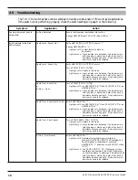
Fault Detection
The TD1 and TD2 have continuous self diagnostics to
ensure the signal from the sensor is within a select range. If
the electronics detect an out of range signal, the switch will
go into fault mode.
In the event of a fault, the red LED will blink and the
relay will de-energize. In the TD2, the mA output will go
to less than 3.6 mA if low level fail-safe is selected or
greater than 22 mA if high level fail-safe is detected.
If a fault is detected, refer to 3.5 Troubleshooting.
3.4
Resistance Values
The following tables provide the expected resistance values
for the sensor. Refer to the indicated figures for pin locations.
Refer to 3.6.2 Probe Replacement for removing bezel and
circuit boards.
Pin
Expected Resistance
1 to 3
90 to 180 ohms
(275 ohms with high temperature probe)
2 to 4
90 to 180 ohms
(275 ohms with high temperature probe)
TD1 (see Figure 12)
Pin
Expected Resistance
1 to 4
90 to 180 ohms
(275 ohms with high temperature probe)
2 to 5
90 to 180 ohms
(275 ohms with high temperature probe)
1 to 2, 3 to 4,
5 to 6
0 to 12 ohms
TD2 – Integral Electronics (see Figure 13)
Pin
Expected Resistance
1 to 3
90 to 180 ohms
(275 ohms with high temperature probe)
2 to 4
90 to 180 ohms
(275 ohms with high temperature probe)
1 to 3, 1 to 4,
2 to 3, 2 to 4
Open
TD2 – Remote Electronic Enclosure (see Figure 14)
4
1
Unmarked Wires
Marked Wires
TB1
Figure 14
TD2 Remote Probe Connections
1
4
1
4
Unmarked Wires
Marked Wires
Figure 12
TD1 Probe Connections
1
6
1
6
Unmarked Wires
Marked Wires
Figure 13
TD2 Probe Connections


