6
1.2
QuickStart Mounting
1.2.1 Transmitter/Antenna
1. The device is manufactured as one unit that includes the
transmitter and antenna.
2. Remove any protective material from the antenna before
installing.
3. Install the transmitter/antenna into the process connection.
If threaded, tighten securely by hand using the housing for
grip. Ensure there is no cross-threading and do not over
tighten as this may cause damage to the plastic threads.
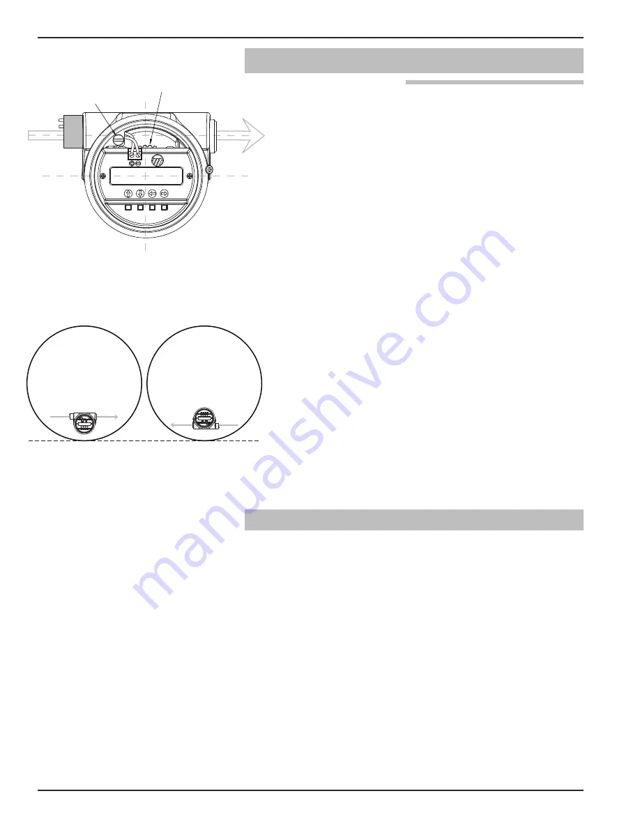
4. Adjust the beam position by turning the internal launcher
adjustment (Figure 2). The internal launcher adjustment is
numbered 1-18 that equates to 10-180 degrees of adjust-
ment; 9 is the midpoint. The polarization pattern is parallel
to the transmitter display when the adjustment mechanism
is in the #11 position (factory default). After positioning the
transmitter display, the launcher should be adjusted so the
polarization pattern is parallel to a line tangent to the near-
est tank wall (Figure 3). Do not optimize the Echo Strength
at one level in the vessel.
• Do not place insulating material around any part of the
Radar transmitter including the antenna process connec-
tion.
1.3
QuickStart Wiring
NOTE: Make sure the electrical wiring to the R82 radar transmitter is
complete and in compliance with all regulations and codes.
1. Remove the cover of the wiring compartment.
2. Attach a conduit fitting and mount the conduit plug in the
spare opening. Pull the power supply wire through the con-
duit fitting.
3. Connect shield to an earth ground at power supply and
leave floating at the transmitter.
4. Connect the positive supply wire to the (+) terminal and the
negative supply wire to the (-) terminal.
5. Seal conduit to prevent ingress of moisture.
6. Replace cover of the transmitter.
58-610 Model R82 Radar Transmitter
Figure 2
Polarization pattern when launcher
is in the #11 Position (default)
Ground
Launcher Adjustment
in #11 Position (Default)
Tangent Line
Figure 3
Polarization shown parallel to tangent
line; either orientation is acceptable


