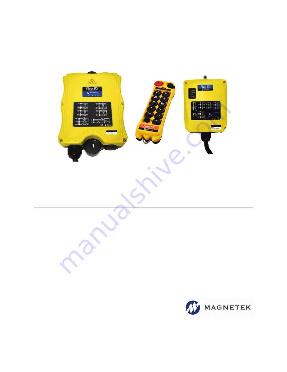
Flex EM/EX HazLoc System
Radio Control Equipment
Instruction Manual
Part Number: 191-90002-M0090F R01
June 2019
©Copyright 2019 Magnetek Material Handling
Page 1: ...Flex EM EX HazLoc System Radio Control Equipment Instruction Manual Part Number 191 90002 M0090F R01 June 2019 Copyright 2019 Magnetek Material Handling...
Page 2: ...Flex EM EX HazLoc System Instruction Manual May 2019 Page 2 of 62 Page Intentionally Left Blank...
Page 3: ...17 3 2 2 External Illustration EM 18 3 2 3 Internal Illustration EX 19 3 2 4 Internal Illustration EM 20 4 Function Settings 21 4 1 Transmitter Handset 21 4 1 1 System Channel Settings 21 4 1 2 Pushb...
Page 4: ...Only 56 7 1 6 Automatic Channel Scanning Operating Procedure All Systems 56 7 1 7 Changing Transmitter Batteries 57 7 2 Status Light Indicators and Warnings 58 7 2 1 Transmitter STATUS Light Indicatio...
Page 5: ...8 8178 Website www magnetek com E mail mhcustomerservice magnetek com Fax Numbers Main 800 298 3503 Sales 262 783 3510 Service 262 783 3508 2019 MAGNETEK All rights reserved This notice applies to all...
Page 6: ...up the crane to change receiver channels Over 1 million unique ID codes 20 bit Every Flex system has its own unique ID codes and serial number no repeats Advanced controls The Flex system utilizes adv...
Page 7: ...s of the equipment where the radio system is used Plant safety rules and procedures of the employers and the owners of facilities where the Magnetek Products are being used Regulations issued by the O...
Page 8: ...es or regulations of any applicable local state or federal governing organizations Always follow your local lockout and tagout procedure when maintaining any radio equipment The following information...
Page 9: ...y be suffering from a disorder or illness that may cause them to lose control of the equipment is taking any medication that may cause loss of equipment control or is under the influence of alcohol or...
Page 10: ...test the transmitter emergency stop and all warning devices prior to operation testing should be done on each shift without a load be thoroughly trained and knowledgeable in proper and safe operation...
Page 11: ...nsmitter in use has been turned off taken out of the service area and secured 2 5 Pre Operation Test At the start of each work shift or when a new operator takes control of the equipment operators sho...
Page 12: ...operation and storage i e not in direct sunlight or close to a heating source 2 8 Battery Disposal Before disposing of batteries consult local and governmental regulatory requirements for proper dispo...
Page 13: ...seated properly in the sprockets drum or sheave leave any load unattended while lifted WARNING All equipment must have a mainline contactor installed and all tracked cranes hoists lifting devices and...
Page 14: ...he Status LED on the transmitter for any signs of low battery power see Section 7 2 on page 58 Check the Status LED on the transmitter for any signs of irregularities see Section 7 2 on page 58 Make s...
Page 15: ...switch on 8EX AB transmitters Pushbutton 12 will be an A B A B selector rotary switch on 12EX AB transmitters 1 Emergency Stop Button 11 Pushbutton 5 2 Removable Power Key Switch 12 Pushbutton 7 3 Pu...
Page 16: ...ters are with the pushbuttons The Flex EM transmitters have single step speed pushbuttons while the Flex EX have two step speed pushbuttons Also available are 8EX AB and 12EX AB which will include a s...
Page 17: ...e 2019 Page 17 of 62 3 2 Receiver Unit 3 2 1 External Illustration EX Fig 3 1 Shock Mount 6 COM LED Display 2 External Antenna Jack 7 Output Contact Diagram 3 Power LED Display 8 System Information 4...
Page 18: ...truction Manual June 2019 Page 18 of 62 3 2 2 External Illustration EM Fig 4 1 External Antenna Jack 5 COM LED Display 2 Power LED Display 6 Output Contact Diagram 3 Status LED Display 7 Cord Grip 4 S...
Page 19: ...Flex EM EX HazLoc System Instruction Manual June 2019 Page 19 of 62 3 2 3 Internal Illustration EX Fig 5 1 AC Line Filter 4 Decoder Module 2 Power Transformer 5 Output Relay Board 3 Receiving Module...
Page 20: ...ruction Manual June 2019 Page 20 of 62 3 2 4 Internal Illustration EM Fig 6 1 Receiving Module 3 AC Line Filter Board 2 Decoder Relay Board 4 Power Transformer I CHIP PORT 1 2 3 4 JP7 JP6 JP5 JP4 JP3...
Page 21: ...amming see Fig 8 The system channels table in Section 5 on page 47 illustrates which dipswitch setting corresponds to which channel Once the transmitter channel is altered be sure to change the receiv...
Page 22: ...the shaded boxes in the table below illustrate which LED on the transmitter will illuminate when the designated pushbutton PB7 PB12 is pressed Fig 9 8 Button Transmitter NOTE PB8 is not available on...
Page 23: ...selector sequence A B A B A B Type B selector sequence Off A B Off A B Type C selector sequence A B A B A B A B Type D selector sequence Off A B A B Off A B A B NOTE These settings are not available...
Page 24: ...10 D 1 2 Normal Normal Normal Normal Normal 00110011 Normal A 3 4 Normal Normal Normal Normal 00110100 Normal B 3 4 Normal Normal Normal Normal 00110101 Normal C 3 4 Normal Normal Normal Normal 001101...
Page 25: ...ormal D 3 4 Normal Normal 01001001 Normal Normal A 1 2 A 3 4 Normal Normal 01001010 Normal Normal A 1 2 B 3 4 Normal Normal 01001011 Normal Normal A 1 2 C 3 4 Normal Normal 01001100 Normal Normal A 1...
Page 26: ...see JP4 and JP5 jumper settings in Section 4 2 5 on page 43 With inline pushbutton configuration PB1 and PB2 still correspond to output relay K1 K4 PB3 and PB4 correspond to relay K5 K8 etc Fig 10 NO...
Page 27: ...Normal LED 3 LED 4 00010101 Normal LED 2 LED 3 LED 4 00010110 LED 1 LED 2 LED 3 LED 4 DIP PB7 PB8 PB9 PB10 PB11 PB12 00000000 Normal Normal Normal Normal Normal Normal 00000101 Normal Normal Normal LE...
Page 28: ...B5 PB8 Pushbutton number Normal Normal momentary contact LED 1 LED 4 Transmitter toggled with designated LED Display DIP PB5 PB6 PB7 PB8 01110011 Normal Normal A 1 2 Normal 01110100 Normal Normal B 1...
Page 29: ...00110101 Normal C 3 4 Normal Normal 00110110 Normal D 3 4 Normal Normal 01110111 A 1 2 A 3 4 Normal Normal 01111000 A 1 2 B 3 4 Normal Normal 01111001 A 1 2 C 3 4 Normal Normal 01111010 A 1 2 D 3 4 N...
Page 30: ...ormal 10001011 Normal B 1 2 D 3 4 Normal 10001100 Normal C 1 2 C 3 4 Normal 10001101 Normal C 1 2 D 3 4 Normal 10001110 Normal D 1 2 D 3 4 Normal 10001111 Normal Normal A 1 2 Normal 10010000 Normal No...
Page 31: ...B3 and rotate the power key to the START position at the same time A series of green and red blinks will appear on the Status LED show ing the current channel setting A green blink represents the tens...
Page 32: ...and then press and hold PB1 PB2 PB3 and PB4 simultaneously Rotate the power key to the START position 2 A solid orange light will appear on the Status LED indicating that you are in the security code...
Page 33: ...re set to all 1 If both dipswitches are set to all 1 then the transmitter will operate according to the pushbutton configurations and channel stored inside the I CHIP If both the Channel and Function...
Page 34: ...e receiver module see Fig 11 Only the first six 6 positions are used for channel programming see Fig 12 The system channels table in Section 5 on page 47 illustrates which dipswitch setting correspond...
Page 35: ...nd 2nd speed output relays Output relays with Forward 1st speed F1 Reverse 1st speed R1 Forward 2nd speed F2 and Reverse 2nd speed R2 Forward and Reverse 2nd speed with separate output relays 4 2 2 2...
Page 36: ...nfiguration with Forward and Fast output relays engaged at 2nd speed 5 4 output relay configuration with Forward Slow and Fast output relays engaged at 2nd speed R2 F2 R1 F1 R2 F2 R1 F1 Forward 1st sp...
Page 37: ...orresponds to that pushbutton will open see Section 4 2 4 on page 39 on how to set to this function This type of contact usually applies to external applications such as horns or buzzers 4 2 2 7 Toggl...
Page 38: ...e Flex system the system preset at channel 62 is ineffective because the 2nd transmitter cannot be set to Ch 63 If your system is preset at Ch 62 be sure to change it to another channel 4 2 3 Receiver...
Page 39: ...or PB9 and PB10 on the transmitter handset or K1 and K2 or K5 and K6 or K9 and K10 on the decoder relay board dip positions 5 8 correspond to PB3 and PB4 or PB7 and PB8 or PB11 and PB12 on the transm...
Page 40: ...lay 4 0000010 Closed Closed Relay Action at 2nd Speed shared 2nd speed relay 3 0000011 Opened Closed Relay Action at 2nd Speed separate 2nd speed relay 4 0000100 Forward and Fast output relays engaged...
Page 41: ...n the function will not operate correctly The toggle operation can only be set in either the transmitter or the receiver not both Dip Settings Function Descriptions of Relays Used 0100010 Closed Close...
Page 42: ...d 8 to the 10 position 2 channel scanning see Section 4 2 2 10 on page 38 NOTE When set to Auxiliary Stop be sure JP3 is inserted see Section 4 2 5 on page 43 Function Code Dip Position Setting 1 Dip...
Page 43: ...M system jumpers 1 7 are located on the decoder relay board between the receiving RF module and the output relays see Fig 17 For an EX system jumpers 1 7 are located on the decoder module above the si...
Page 44: ...fter E Stop reset and after system inactivity JP3 Inserted Rotate the power key switch to START position to activate the receiver MAIN at system startup after E Stop reset and after system inactivity...
Page 45: ...module turns a solid green within 2 seconds and then take the I CHIP out of the programming port programming completed At this time the I CHIP should also possess the same serial number ID code as the...
Page 46: ...with 24 42 48VAC power supply For system with 12 24VDC power supply Fuse Ratings For an EM System For an EX System FUSE 110 120VAC 220 240VAC 380 400VAC 410 460VAC 24VAC 42 48VAC 12 24VDC F1 F8 5 0A c...
Page 47: ...10 433 225MHZ 001010 42 434 025MHZ 101010 11 433 250MHZ 001011 43 434 050MHZ 101011 12 433 275MHZ 001100 44 434 075MHZ 101100 13 433 300MHZ 001101 45 434 100MHZ 101101 14 433 325MHZ 001110 46 434 125...
Page 48: ...he positive charge Wire 2 is for GROUND Wire 6 is for Normal Close and wire 8 is for Normal Open MAIN output Due to the possibility of voltage spikes on the contactors suppressors are required on cont...
Page 49: ...nects to wire 36 and B connects to wire 38 For different voltage settings see Section 4 2 7 on page 46 For F9 and F10 power fuse ratings see Section 4 2 7 on page 46 For 12 24VDC power supply wire 1 c...
Page 50: ...channels 2 Make sure the receiver is not set to the same channel as any other systems in use in the surrounding area 3 Make sure that the crane or equipment is working properly prior to installation 4...
Page 51: ...Flex EM EX HazLoc System Instruction Manual June 2019 Page 51 of 62 Fig 23 Flex EX...
Page 52: ...far away from a variable frequency drive as possible 3 Ensure the selected location has adequate space to accommodate the receiver If an external antenna is used always locate the receiver where the...
Page 53: ...tion 6 1 on page 48 and Section 6 2 on page 49 6 5 System Testing 1 Turn on the power source to the receiver and test the MAIN relay output by pressing the red emergency stop button and observe that i...
Page 54: ...e transmitter handset and rotate it clockwise to the ON position 3 After turning on the transmitter power check the Status LED on the transmitter handset for any sign of system irregularities see Sect...
Page 55: ...isconnected temporarily depends on JP1 JP2 settings see Section 4 2 5 on page 43 To resume operation rotate the power key switch to the START position to reconnect the receiver MAIN 8 Turn off the tra...
Page 56: ...h pushbutton during operation rotate the power key to the Catch position for up to 2 seconds to regain control 7 1 6 Automatic Channel Scanning Operating Procedure All Systems After changing the trans...
Page 57: ...ved for use with the Flex HazLoc system Change the transmitter batteries by unscrewing the battery cover located on the backside of the transmitter see Fig 26 During battery installation make sure tha...
Page 58: ...on occurs 2 red blinks type 3 above find out which pushbutton is defective by pressing all the pushbuttons on the transmitter one at a time If the pushbutton is in good working order the LED will not...
Page 59: ...with receiver MAIN deactivated 4 2 red blinks Receiver MAIN jammed or defective 5 Fast red blinks Incorrect transmitter serial number ID code 6 Solid red Receiver under voltage LV output relay activa...
Page 60: ...e sure the startup procedure is initiated within 100 meters 300 feet from the receiver location No response when transmitter pushbut ton is pressed damaged hardware Defective transmitting and receivin...
Page 61: ...conds average Transmitting Power 1 0 mW Enclosure Type NEMA 4X Enclosure Rating IP66 Output Contact Rating 250V 8 Amps Transmitter Operating Voltage 3 0VDC Receiver Power Consumption EM 7 0 VA EX 11 0...
Page 62: ...60529 1992 EN ISO 13849 1 2008 EN 13557 2003 A2 2008 EN 60079 0 2012 EN 60079 11 2012 ATEX speci c informa on Product is in conformity with the EC type examina on cer cate DEMKO 16 ATEX 1601X For Equi...