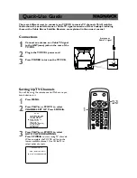
1-1-3
P7752SP
< ATSC >
Measurement at Speaker (Audio)
Note:
Nominal specifications represent the design specifications. All units should be able to approximate these.
Some will exceed and some may drop slightly below these specifications. Limit specifications represent
the absolute worst condition that still might be considered acceptable. In no case should a unit fail to meet
limit specifications.
Description
Condition
Unit
Nominal
Limit
1. RECEIVED FREQ. RANGE
(-28dBm)
+
kHz
150
>100
–
kHz
150
>100
2. ATSC DYNAMIC RANGE (min./max.)
VHF LOW BAND. CH.4
VHF HI BAND. CH.10
UHF BAND. CH.41
---
dB
µ
V
dB
µ
V
dB
µ
V
26/114
26/114
28/118
32/108
32/108
34/112
3. ATSC SUSCEPTIBILITY TO
RANDOM NOISE
VHF LOW BAND. CH.4
VHF HI BAND. CH.10
UHF BAND. CH.41
---
dB
dB
dB
20
20
20
<26
<26
<26
4. NTSC CO-CHANNEL INTERFERENCE
VHF LOW BAND. CH.4
VHF HI BAND. CH.10
UHF BAND. CH.41
---
dB
dB
dB
0
0
0
>-6
>-6
>-6
5. MULTIPATH
A
dB
0
<6
B
dB
0
<6
C
dB
0
<6
D
dB
0
<6
E
dB
0
<6
F
dB
0
<6
FF
dB
0
<6
G
dB
0
<6
6. Audio S/N (0dBfs)
L
dB
60
>50
R
dB
60
>50
7. Audio DIST. (0dBfs)
L
%
0.1
<3
R
%
0.1
<3
Summary of Contents for CT202MW8
Page 44: ...1 11 3 Main 1 6 Sensor Schematic Diagram TV VCR Section P7754SCM1...
Page 45: ...1 11 4 P7754SCM2 Main 2 6 Schematic Diagram TV VCR Section...
Page 46: ...1 11 5 P7754SCM3 Main 3 6 Schematic Diagram TV VCR Section...
Page 47: ...1 11 6 Main 4 6 Schematic Diagram TV VCR Section P7754SCM4...
Page 48: ...1 11 7 P7754SCM5 Main 5 6 Junction A Schematic Diagram TV VCR Section...
Page 50: ...1 11 9 P7754SCSUB1 Sub 1 3 Schematic Diagram TV VCR Section...
Page 51: ...1 11 10 Sub 2 3 Schematic Diagram TV VCR Section P7754SCSUB2...
Page 52: ...1 11 11 Sub 3 3 Schematic Diagram TV VCR Section P7754SCSUB3...
Page 54: ...1 11 13 P7754SCDT1 DTV Module 1 2 Schematic Diagram TV VCR Section...
Page 56: ...1 11 15 P7754SCD1 DVD Main 1 3 Schematic Diagram DVD Section...
Page 57: ...1 11 16 P7754SCD2 DVD Main 2 3 Schematic Diagram DVD Section...
Page 58: ...1 11 17 P7754SCD3 DVD Main 3 3 Schematic Diagram DVD Section...
Page 78: ...1 17 2 P7754PEX Packing FRONT S4 S1 X1 Tape X2 X3 S3 S6 S7 S2 Packing Tape...