SERVICE MANUAL
Main Section
I
Specifications
I
Preparation for Servicing
I
Adjustment Procedures
I
Schematic Diagrams
I
CBA’s
I
Exploded Views
I
Parts List
When servicing the deck
mechanism, refer to MK14 Deck
Mechanism Section.
Deck Mechanism Part No.:
N2466FT
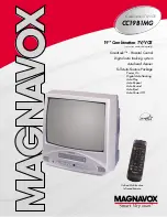
This service manual is for the MWC24T5
version B model, which is different from the
previous model. For MWC24T5 version B
model, a suffix “B” is printed on the rating label
on the back of the unit. Refer to the rating label
illustration at right.
Rating Label
Suffix "B"
24
″
COLOR
TV/DVD/VCR
MWC24T5
Summary of Contents for MWC24T5
Page 41: ...1 11 3 Main 1 6 Sensor Schematic Diagram TV VCR Section T2202SCM1...
Page 42: ...1 11 4 T2202SCM2 Main 2 6 Schematic Diagram TV VCR Section...
Page 43: ...1 11 5 T2202SCM3 Main 3 6 Schematic Diagram TV VCR Section...
Page 44: ...1 11 6 Main 4 6 Schematic Diagram TV VCR Section T2202SCM4...
Page 45: ...1 11 7 T2202SCM5 Main 5 6 Junction A Schematic Diagram TV VCR Section...
Page 47: ...1 11 9 T2202SCSUB1 Sub 1 2 Schematic Diagram TV VCR Section...
Page 48: ...1 11 10 Sub 2 2 Schematic Diagram TV VCR Section T2202SCSUB2...
Page 50: ...1 11 12 T2202SCD1 DVD Main 1 3 Schematic Diagram DVD Section...
Page 51: ...1 11 13 T2202SCD2 DVD Main 2 3 Schematic Diagram DVD Section...
Page 52: ...1 11 14 T2202SCD3 DVD Main 3 3 Schematic Diagram DVD Section...
Page 72: ...1 17 2 T2203PEX Packing FRONT S4 S1 X1 Tape X4 X2 X3 S3 S6 S7 S2 Packing Tape...
Page 82: ...MWC24T5 T2202UC 2006 04 06...