background image

Contents

Chapter

Sec. 1: Adjustment Procedures

Schematic Diagrams and CBA's
Exploded Views
Mechanical and Electrical Parts Lists

Sec. 2: Standard Maintenance

Mechanism Alignment Procedures
Disassembly / Assembly of Mechanism
Deck Exploded Views
Deck Parts List

Survey of versions:

Published by FU-KC 0524 Service AV Systems          Printed in The Netherlands          Subject to modification
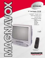
/17                 NTSC

TV-VCR Combination

MC132EMG/

17

 c Copyright 2005 Philips Consumer Electronics B.V. Eindhoven, The Netherlands.

All rights reserved. No part of this publication may be reproduced, stored in a retrieval 
system or transmitted, in any form or by any means, electronic, mechanical, photocopying, 
or otherwise without the prior permission of Philips.

EN  3139 785 31370

Third Generation

Service Manual

Service

Service

Service

This service manual is for MC132EMG/17 Third 
Generation model, which is different from the 
previous generation MC132EMG/17 models. 

For Third Generation model, the serial number begins 
with DD5Axxxxxxxxxx. 

Refer to the rating label illustration at right.

rating label

serial number

www.freeservicemanuals.info

It`s Free

Summary of Contents for MC132EMG/17

Page 1: ...nics B V Eindhoven The Netherlands All rights reserved No part of this publication may be reproduced stored in a retrieval system or transmitted in any form or by any means electronic mechanical photo...

Page 2: ...ZE THE TV VCR COMBINATION 1 7 1 BLOCK DIAGRAMS 1 8 1 SCHEMATIC DIAGRAMS CBA S AND TEST POINTS 1 9 1 WAVEFORMS 1 10 1 WIRING DIAGRAM 1 11 1 SYSTEM CONTROL TIMING CHARTS 1 12 1 IC PIN FUNCTION DESCRIPTI...

Page 3: ...ble to the coaxial connector If the measured resistance is less than 1 0 megohm or greater than 5 2 megohm an abnormality exists that must be corrected before the instrument is returned to the custome...

Page 4: ...l between the chassis and a known earth ground b Some TV receiver chassis normally have 85V AC RMS between chassis and earth ground regardless of the AC plug polarity This chassis can be safety servic...

Page 5: ...cts screws solder droplets etc do not remain inside the set K Crimp type wire connector When replacing the power transformer in sets where the connections between the power cord and power transformer...

Page 6: ...ts RF terminals antenna terminals video and audio input and output terminals microphone jacks earphone jacks etc is lower than or equal to the specified value in the table below Measuring Method Power...

Page 7: ...special logo not always indicated One must treat all sets from onwards according to the next rule Serial Number gives a 9 digit Digit 2 3 shows the WEEK and digit 4 shows the YEAR So from onwards fro...

Page 8: ...mponents all needed spare parts will be available till the end of the service period For repair of such sets nothing changes On our website www atyourservice ce Philips com you find more information t...

Page 9: ...at pack IC and heat up Then remove glue will be melted Fig S 1 6 4 Release the flat pack IC from the CBA using tweezers Fig S 1 6 CAUTION 1 The Flat Pack IC shape may differ by models Use an appropria...

Page 10: ...pack IC you can remove it easily Fig S 1 3 2 Affix the wire to a workbench or solid mounting point as shown in Fig S 1 5 3 While heating the pins using a fine tip soldering iron or hot air blower pul...

Page 11: ...ential difference caused by electrostatic charge during unpacking or repair work 1 Ground for Human Body Be sure to wear a grounding band 1 M that is properly grounded to remove any static electricity...

Page 12: ...2 1 To eject the tape press the STOP EJECT button on the unit or Remote Control 2 When you want to record during the Service mode press the Rec button while depressing SW211 REC SAFETY SW on the Main...

Page 13: ...1 4 1 T5515IB OPERATING CONTROLS AND FUNCTIONS www freeservicemanuals info It s Free...

Page 14: ...1 4 2 T5515IB www freeservicemanuals info It s Free...

Page 15: ...1 4 3 T5515IB www freeservicemanuals info It s Free...

Page 16: ...the following Reference Notes in the Table Reference Notes in the Table 1 Removal of the Rear Cabinet Remove screws 4 S 1 and S 2 2 CAUTION Discharge the Anode Lead of the CRT with the CRT Ground Wir...

Page 17: ...1 5 2 T5515DC 1 Rear Cabinet S 1 S 1 S 1 S 2 Fig D1 1 Rear Cabinet S 1 S 2 S 1 S 1 S 1 Fig D2 www freeservicemanuals info It s Free...

Page 18: ...1 5 3 T5515DC 2 Tray Chassis 3 Deck Unit S 3 S 3 S 3 4 Main CBA S 6 S 5 S 4 S 6 S 6 S 6 S 7 Fig D3 www freeservicemanuals info It s Free...

Page 19: ...1 5 4 T5515DC S 8 S 8 S 8 S 8 ANODE CAP 5 CRT CRT CBA Fig D4 www freeservicemanuals info It s Free...

Page 20: ...CN801 CN601 CN571 FOCUS CRT CBA AC CORD CL403 FE HEAD CYLINDER ASSEMBLY ACE HEAD ASSEMBLY CAPSTAN MOTOR DECK UNIT MAIN CBA CL401 CL502B CL201 CL402 CL501B CRT ANODE GND TO SPEAKER TO DEGAUSS COIL Fig...

Page 21: ...be used as service remote control unit How to Set Up the Service mode Service mode 1 Use the service remote control unit 2 Turn the power on at the unit 3 Press SLEEP WAKE UP button on the service rem...

Page 22: ...34 kHz 300 Hz 6 Turn the power off and on again 4 C Trap Adjustment Purpose To get minimum leakage of the color signal carrier Symptom of Misadjustment If C Trap Adjustment is incorrect stripes will a...

Page 23: ...ote control unit seven times to show C ANG on the display 3 Y DL Time TV Adjustment Select 2 by pressing CH o p buttons on the service remote control Y DL Time EXT Adjustment Select 2 by pressing CH o...

Page 24: ...sition and size of screen image Symptom of Misadjustment Horizontal position and size of screen image may not be properly displayed 1 Enter the Service mode See page 1 6 1 Press 8 button on the servic...

Page 25: ...hen press 4 button on the service remote control unit for Red adjustment Press 5 button on the service remote control unit for Blue adjustment 12 In each color mode press CH o p buttons to adjust the...

Page 26: ...he microcomputer The following 2 adjustments normally are not attempted in the field They should be done only when replacing the CRT then adjust as a preparation 14 Purity Adjustment Purpose To obtain...

Page 27: ...enter of the screen by rotating RB G C P Magnet See Fig 9 4 Fix the C P Magnets by tightening the Ring Lock 5 Remove the DY Wedges and slightly tilt the Deflection Yoke horizontally and vertically to...

Page 28: ...Test Points TP301 V OUT VR601 B ADJ D613 Cathode B Adjustment TP201 CTL TP202 RF SW J271 B OUT TP402 V ENV TP402 V ENV Main CBA UPPER FOCUS VR LOWER SCREEN VR R583 H Adjustment C613 GND B Adjustment w...

Page 29: ...to Set up the Service mode on page 1 6 1 4 Press VOL p button on the service remote control unit twice and confirm that OSD indication is 7F FF If needed set it to become 7F FF by pressing CH o p but...

Page 30: ...ROMA TUNER BLOCK SDA SCL IC202 WF3 5 5 CTL 6 6 CTL M M LOADING MOTOR CAPSTAN MOTOR SENSOR CBA ST SENSOR SENSOR CBA END SENSOR CL201 C FG C CONT D PFG 90 76 87 LD CONT 82 D CONT 77 P ON 12V P ON 5V CAP...

Page 31: ...BLY VIDEO AGC R P FBC Y C MIX CCD 1H DELAY R P YNR COMB FILTER CHROMINANCE SIGNAL PROCESS IC401 VIDEO SIGNAL PROCESS HEAD AMP 26 REC VIDEO SIGNAL PB VIDEO SIGNAL MODE SP REC 57 QV QH 6dB AMP TO SERVO...

Page 32: ...EM CONTROL BLOCK TUNER REC AMP AUTO BIAS LINE AMP MUTE P R ALC TUNER LINE D REC H A MUTE TO SERVO SYSTEM CONTROL BLOCK WF8 32 EQ AMP SP LP ON 5 24 14 15 26 21 LINE VCR 10 6 8 9 58 11 5 4 3 78 76 2 MUT...

Page 33: ...ENT MONITORING CHROMA BPF SYNC SEPARATION LUMA SIGNAL PROCESS CIRCUIT CHROMA SIGNAL PROCESS CIRCUIT H SYNC PROCESS CIRCUIT V SYNC PROCESS CIRCUIT OSD MIX RBG MATRIX BLIGHT DRIVE AMP HV BLANKING TUNER...

Page 34: ...TO POWER SUPPLY BLOCK DEF B H OUTPUT V RAMP NF 5 4 3 1 WF12 WF15 WF14 WF16 WF13 RED AMP Mode SP REC CL502A VCC 6 7 1 3 2 5 1 5 3 4 6 9 7 10 8 11 S F HV 3 3 HEATER 1 1 160V 2 RED 3 GREEN 4 BLUE NOTE FO...

Page 35: ...THE PCB WIRE IS SOLDERED DIRECTLY TEST POINT INFORMATION INDICATES A TEST POINT WITH A JUMPER WIRE ACROSS A HOLE IN THE PCB USED TO INDICATE A TEST POINT WITH A COMPONENT LEAD ON FOIL SIDE USED TO IND...

Page 36: ...presented by the following symbols Notes 1 Do not use the part number shown on these drawings for ordering The correct part number is shown in the parts list and may be slightly different or amended s...

Page 37: ...224 D 2 L202 D 2 R239 C 1 SW205 A 4 C225 D 2 L211 F 3 R240 C 1 SW206 A 4 C231 D 3 R241 D 1 SW207 A 4 C232 D 3 Q205 B 1 R243 D 2 SW208 A 4 C233 D 1 Q206 D 3 R244 D 2 SW209 A 4 C235 D 3 R245 D 2 SW210 A...

Page 38: ...2 5 PLAY mode REC mode Voltage indications for PLAY and REC modes on the Schematic Diagrams are as shown below 1 2 3 5 0 The same voltage for both PLAY REC modes Indicates that the voltage is not cons...

Page 39: ...PLAY mode REC mode Voltage indications for PLAY and REC modes on the Schematic Diagrams are as shown below 1 2 3 5 0 The same voltage for both PLAY REC modes Indicates that the voltage is not consist...

Page 40: ...2 H 2 R407 I 4 R865 I 2 C427 J 4 C873 H 2 R408 I 4 R866 I 1 C428 J 4 C874 G 2 R409 J 1 R867 I 1 C429 J 4 C875 G 2 R410 J 2 R868 I 1 C430 J 4 R414 J 2 R871 H 1 C431 J 4 CL401 G 3 R415 J 2 R872 H 2 C432...

Page 41: ...O 1 C046 P 1 C339 O 2 R337 O 2 C047 Q 2 C340 N 1 J219 P 2 R338 O 2 C048 Q 1 C342 O 1 R002 Q 1 R339 O 1 C049 P 3 C351 O 2 R003 P 1 R340 O 1 C052 Q 2 C352 P 1 R032 Q 3 R701 M 4 C053 Q 2 C353 O 2 R033 P...

Page 42: ...PLAY mode REC mode Voltage indications for PLAY and REC modes on the Schematic Diagrams are as shown below 1 2 3 5 0 The same voltage for both PLAY REC modes Indicates that the voltage is not consist...

Page 43: ...me type de 4A 125V 4A 125V CAUTION Fixed voltage or Auto voltage selectable power supply circuit is used in this unit If Main Fuse F601 is blown check to see that all components in the power supply ci...

Page 44: ...2 C623 V 2 D627 U 2 R607 W 2 R659 T 2 C624 U 3 D628 U 2 R608 W 2 R660 T 1 C625 U 2 D629 U 3 R610 W 2 R661 U 1 C626 U 2 D631 T 2 R613 W 2 R662 U 2 C627 S 1 D632 S 2 R614 W 2 R665 T 1 C628 T 3 D633 S 2...

Page 45: ...C551 Y 3 R571 Z 3 R597 Z 1 C592 AA 2 R573 Z 3 R598 AA 2 C593 AA 2 Q571 AA 2 R574 Z 2 R599 AA 2 C594 Z 2 Q572 Z 3 R575 Z 2 Q591 Z 2 R576 Z 2 BC571 AA 2 CL501B BB 3 R577 Z 3 T571 AA 3 CL502B BB 2 R544 Z...

Page 46: ...5 PLAY mode REC mode Voltage indications for PLAY and REC modes on the Schematic Diagrams are as shown below 1 2 3 5 0 The same voltage for both PLAY REC modes Indicates that the voltage is not consi...

Page 47: ...D 4 C250 C 1 C431 B 3 C633 C 4 D315 B 3 IC301 B 4 R037 D 4 C252 C 1 C432 B 3 C634 D 4 D401 C 2 IC401 C 3 R038 D 4 C253 C 1 C435 C 3 C635 C 4 D552 D 2 IC551 D 2 R039 D 4 C254 C 1 C436 B 3 C636 D 3 D571...

Page 48: ...ltage or Auto voltage selectable power supply circuit is used in this unit If Main Fuse F601 is blown check to see that all components in the power supply circuit are not defective before you connect...

Page 49: ...ransformer is required NOTE The voltage for parts in hot circuit is measured using hot GND as a common terminal For continued protection against risk of fire replace only with same type 4 A 125V fuse...

Page 50: ...B 2 R527 B 1 C502 B 1 R511 B 2 R530 A 2 C511 B 2 R512 B 2 R531 B 2 C521 B 2 R513 B 2 R532 A 2 C531 B 2 R515 B 1 R533 B 2 R516 B 1 R535 A 1 CL501A A 1 R517 B 1 R536 A 1 CL502A B 1 R520 B 2 R537 B 1 CN5...

Page 51: ...s IC401 PIN 32 Upper WF6 Lower WF1 1DIV 0 2V 2DIV 5V 5ms TP402 V ENV WF5 1DIV 0 5V 20 s TP301 V OUT WF8 1DIV 0 5V 0 5ms TP401 A OUT WF7 1DIV 0 2V 0 5ms IC001PIN 7 WF9 1DIV 0 5V 0 5ms IC401 PIN 9 WF11...

Page 52: ...FG GND 7 LD CONT 8 D CONT 9 D PFG 10 M GND 11 D L 12V 12 D L 15V 6 AE H 5 AE H FE H 4 A COM 3 A PB REC 2 CTL 1 CTL 1 SPEAKER 2 SP GND 1 GND 2 RED 3 GREEN 4 BLUE 1 GND 2 RED 3 GREEN 4 BULE 1 160V 2 GN...

Page 53: ...IN NO CL EJ SS SS AU AU TL LD SW CL SS LD CONT C DRIVE Z ON ON C F R DRUM ROTATION P ON A MUTE H D REC H D PB H PAUSE ON PAUSE PAUSE ON PAUSE OFF PAUSE OFF AU AL AU SF SM EJ AU RS SF SM TL FB AL SB 1...

Page 54: ...V LD REV LD FWD LD FWD LD FWD LD FWD LD FWD LD FWD LD FWD REC PAUSE REC REC REW LD REV LD REV LD REV LD REV LD REV LD REV LD REV PAUSE REC or PAUSE STOP EJECT STOP EJECT STOP EJECT 2 STOP A FF STOP A...

Page 55: ...REC SAFETY Record Protection Tab Detection 34 IN RESET System Reset Signal Reset L 35 IN XC IN Sub Clock 32 kHz 36 OUT XC OUT Sub Clock 32 kHz 37 TIMER 5V Vcc 38 IN X IN Main Clock Input 39 OUT X OUT...

Page 56: ...Down Detector Signal 85 NU Not Used 86 GND GND 87 IN C FG Capstan Motor Rotation Detection Pulse 88 GND GND AMP 89 NU Not Used 90 IN D PFG Drum Motor Pulse Generator 91 NU Not Used 92 OUT AMP VREF IN...

Page 57: ...1F4M T KTA1267 GR KTA1271 Y KTC3199 GR KTC3207 2SC1815 GR TPE2 2SC2120 O Y TPE2 2SC3331 T U KRA103M KTC3203 Y LA78040A AN15524A 2SC5884000RF TT2138LS YB11 MID 32A22F PT204 6B 12 KA7805A KIA7805API UA7...

Page 58: ...0 14390 TACT SWITCH SKQNAED010 SW207 9965 000 29665 TACTILE SWITCH KSHG612BT SW208 9965 000 14390 TACT SWITCH SKQNAED010 SW208 9965 000 29665 TACTILE SWITCH KSHG612BT SW209 9965 000 14390 TACT SWITCH...

Page 59: ...ET OXIDE RES 1W J 12 OHM COILS L033 9965 000 29657 INDUCTOR 15UH J 26T L033 4822 157 10648 15UH L202 9965 000 13857 INDUCTOR 0 10UH K 26T OR L211 9965 000 05627 CHOKE COIL 47UH K L211 9965 000 05702 C...

Page 60: ...4822 130 32778 1SS133 D613 9965 000 29164 DIODE 15KRA40 D613 9965 000 28912 RECOVERY DIODE ERC18 04 D614 9965 000 13880 DIODE FR104 B OR D614 9965 000 28913 DIODE FR104BB D615 9965 000 28923 DIODE 1ZC...

Page 61: ...21660 TOSHIBA 2SC2120 Y Q609 9965 000 21660 TOSHIBA 2SC2120 Y Q610 9965 000 28942 TRANSISTOR 2SC2120 O TPE2 Q610 9965 000 21660 TOSHIBA 2SC2120 Y Q610 9965 000 21660 TOSHIBA 2SC2120 Y Q611 9965 000 0...

Page 62: ...E RES 1W J 15K OHM R530 9965 000 29041 MET OXIDE RES 1W J 15K OHM TRANSISTORS Q511 9965 000 29675 TRANSISTOR 2SC3468 E AE Q511 9965 000 29676 TRANSISTOR 2SC3468 D AE Q511 4822 130 60578 2SC2482 Q511 9...

Page 63: ...1 2 L1 L1 L1 L1 A2 A3 L7 V501 1 L551 Details for L551 and surrounding parts SHINWHA TAPE SGT 730 WHITE SHINWHA TAPE SGT 730 BLACK V501 3 V501 2 L551 DG601 CLN551 A1X See Electrical Parts List for part...

Page 64: ...1 16 2 T5515PEX Packing X3 X4 X2 1 S4 X9 S2 Packing Tape X2 2 X24 1 X24 2 X11 1 X11 2 Packing Tape Packing Tape Packing Tape S6 S3 X1 Tape S1 FRONT S4 www freeservicemanuals info It s Free...

Page 65: ...9965 000 29142 DEFLECTION YOKE CDY M1456S V501 9965 000 29151 CRT A34KPU02XX CRT TYPE G A34JXV70X L551 9965 000 29139 DEFLECTION YOKE LLBY00ZSY002 L551 9965 000 29140 DEFLECTION YOKE KDY3GCE83X L551...

Page 66: ...2 3 1 DISASSEMBLY ASSEMBLY PROCEDURES OF DECK MECHANISM 2 4 1 ALIGNMENT PROCEDURES OF MECHANISM 2 5 1 DECK EXPLODED VIEWS 2 6 1 DECK PARTS LIST 2 7 1 Sec 2 Deck Mechanism Section I Standard Maintenan...

Page 67: ...the parts do all DECK ADJUSTMENTS 3 For the reference numbers listed above refer to Deck Exploded Views Deck Periodic Service Schedule Ref No Part Name 1 000 h 2 000 h 3 000 h 4 000 h B2 Cylinder Ass...

Page 68: ...since it is very thin avoid cleaning it vertically 2 Wait for the cleaned part to dry thoroughly before operating the unit 3 Do not reuse a stained head cleaning stick or a stained chamois cloth Clean...

Page 69: ...001H6 Alignment Tape Back Tension Meter Made in USA Flat Screw Driver Purchase Locally Post Adjustment Screwdriver Metric Thickness Gauges Purchase Locally Lock Screw Driver Purchase Locally Head Clea...

Page 70: ...uide preparations are in the Eject Position 4 Turn the LDG Belt in the appropriate direction shown in Fig M1 until the Moving guide preparations come to the Eject Position Stop turning when the prepar...

Page 71: ...the supply and take up side Guide Rollers Use a blank tape Adjust the height of the Guide Rollers Supply side and take up side Use a blank tape Page 2 3 3 Loading Use a blank tape Adjust the envelope...

Page 72: ...ACE Head Fig M6 1 B X Value Alignment Purpose To obtain maximum PB FM envelope signal at the preset position of the Tracking Control Circuit align the Horizontal Position of the ACE Head Symptom of M...

Page 73: ...he top of the Guide Roller with the Guide Roller Adj Screwdriver 3 If the envelope is as shown in Fig M7 adjust the height of Guide Roller 2 Refer to Fig M3 so that the waveform looks like the one sho...

Page 74: ...to ensure preset position The number of pushes CHANNEL K button to achieve 1 2 level of envelope should match the number of pushes CHANNEL L button from center If required redo the X Value Alignment...

Page 75: ...mbly T DM1 DM6 Desolder 3 S 2 8 8 Loading Motor Assembly T DM1 DM7 Desolder LDG Belt 2 S 3 9 9 ACE Head Assembly T DM1 DM7 S 4 10 2 Tape Guide Arm Assembly T DM1 DM8 1 P 2 11 10 C Door Opener T DM1 DM...

Page 76: ...n 32 25 Loading Arm SP Assembly B DM2 DM14 Refer to Alignment Sec Page 2 5 1 33 32 Loading Arm TU Assembly B DM2 DM14 Refer to Alignment Sec Page 2 5 1 34 2 25 M Brake TU Assembly T DM1 DM15 P 7 Brake...

Page 77: ...2 4 3 N2426FTDA 14 13 11 10 12 7 8 30 40 16 39 38 42 41 43 9 34 15 36 35 29 46 Fig DM1 Top View 32 20 33 24 25 27 26 23 28 31 21 22 Bottom View Fig DM2 www freeservicemanuals info It s Free...

Page 78: ...10 Fig DM4 3 6 6 L 2 Pin A Hole A Pin B Hole B L 1 First insert 6 diagonally in 3 as shown below Then install 6 in 3 while pushing L 1 in a direction of arrow After installing 6 in 3 confirm that pin...

Page 79: ...Fig DM7 Pin of 12 Pin of 10 Groove of 28 View for A When reassembling 10 and 12 confirm that pin of 10 and pin of 12 are in the groove of 28 as shown 28 11 13 12 A 10 L 4 S 4A P 3 P 2 Removal of 11 1...

Page 80: ...12 P 3 Fig B Top view Install pin of 12 in groove of 28 Refer to Fig B 28 Hold 12 and 13 till groove of pin of chassis looks and fit 13 in notch of chassis Then turn a few 13 while holding 12 Refer t...

Page 81: ...stall the spring P 5 to 28 as shown in the left figure and then install 23 while pressing the spring P 5 to the direction of the arrow in the left figure and confirming that the position of the spring...

Page 82: ...ottom View 28 25 28 Top View First tooth on 44 First groove on 28 Installation of 25 When reassembling 28 align the first groove on 28 to the first tooth on 44 as shown Fig DM13 2 Refer to the Alignme...

Page 83: ...2 4 9 N2426FTDA 43 41 42 L 13 Fig DM16 44 45 Slide P 9 Fig DM17 www freeservicemanuals info It s Free...

Page 84: ...lectrical parts Alignment points in Eject Position Alignment 1 Loading Arm SP and TU Assembly Install Loading Arm SP and TU Assembly so that their triangle marks point to each other as shown in Fig AL...

Page 85: ...LIDUS OIL 150 B12 B492 B11 B571 B37 Some Ref Numbers are not in sequence B126 B8 B121 B426 B560 L1450 L1450 L1466 B501 Chassis Assembly Top View Lubricating Point Chassis Assembly Bottom View Lubricat...

Page 86: ...B508 B414 View for A Grease point B516 B559 B52 B134 B133 B568 B565 B417 Some Ref Numbers are not in sequence Bottom Side Grease point B507 B488 B570 B491 B513 B502 Bottom Side Grease point L1151 B52...

Page 87: ...ption Floil G 684G or Multemp MH D Blue grease SLIDUS OIL 150 B563 B300 B562 B482 B355 B354 B483 B425 L1321 B347 L1321 B313 L1341 B303 B555 B514 Some Ref Numbers are not in sequence B361 B359 B529 B36...

Page 88: ...WORM HOLDER MK12 B502 9965 000 17200 CAM GEAR B MK12 B507 9965 000 05342 REEL WASHER MK9 5 2 1 0 5 B508 9965 000 08470 S BRAKE SPRING MK10 B513 9965 000 17201 CAM WASHER MK12 B514 9965 000 08641 SCREW...

Reviews: