1-11-2
X8TN_SC
LIST OF CAUTION, NOTES, AND SYMBOLS USED IN THE SCHEMATIC DIAGRAMS ON
THE FOLLOWING PAGES:
1. CAUTION:
FOR CONTINUED PROTECTION AGAINST RISK OF FIRE, REPLACE ONLY
WITH SAME TYPE_A,_V FUSE.
ATTENTION:
UTILISER UN FUSIBLE DE RECHANGE DE MÊME TYPE DE_A,_V.
2. CAUTION:
Fixed Voltage (or Auto voltage selectable) power supply circuit is used in this unit.
If Main Fuse (F1601) is blown, first check to see that all components in the power supply circuit are not defec-
tive before you connect the AC plug to the AC power supply. Otherwise it may cause some components in the
power supply circuit to fail.
3. Note:
1. Do not use the part number shown on the drawings for ordering. The correct part number is shown in the
parts list, and may be slightly different or amended since the drawings were prepared.
2. To maintain original function and reliability of repaired units, use only original replacement parts which are
listed with their part numbers in the parts list section of the service manual.
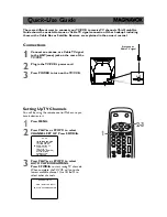
4. Mode: SP/REC
5. Voltage indications on the schematics are as shown below:
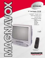
6. How to read converged lines
7. Test Point Information
2
3
1
5.0
(2.5)
PLAY mode
STOP mode
5.0
The same voltage for
both PLAY & STOP modes Indicates that the voltage
is not consistent here.
< DVD Section >
2
3
1
5.0
(2.5)
< 0 >
PLAY mode
REC mode
DVD mode
5.0
The same voltage for
PLAY, REC & DVD
modes
Indicates that the voltage
is not consistent here.
< TV/VCR Section >
Unit: Volts
3
2
1
A
B
C
D
1-B1
1-D3
AREA D3
AREA B1
1-D3
Distinction
Area
Line Number
(1 to 3 digits)
Examples:
1. "1-D3" means that line number "1" goes to the line number
"1" of the area "D3".
2. "1-B1" means that line number "1" goes to the line number
"1" of the area "B1".
: Indicates a test point with a jumper wire across a hole in the PCB.
: Used to indicate a test point with a component lead on foil side.
: Used to indicate a test point with no test pin.
: Used to indicate a test point with a test pin.
Summary of Contents for CT202MW8
Page 44: ...1 11 3 Main 1 6 Sensor Schematic Diagram TV VCR Section P7754SCM1...
Page 45: ...1 11 4 P7754SCM2 Main 2 6 Schematic Diagram TV VCR Section...
Page 46: ...1 11 5 P7754SCM3 Main 3 6 Schematic Diagram TV VCR Section...
Page 47: ...1 11 6 Main 4 6 Schematic Diagram TV VCR Section P7754SCM4...
Page 48: ...1 11 7 P7754SCM5 Main 5 6 Junction A Schematic Diagram TV VCR Section...
Page 50: ...1 11 9 P7754SCSUB1 Sub 1 3 Schematic Diagram TV VCR Section...
Page 51: ...1 11 10 Sub 2 3 Schematic Diagram TV VCR Section P7754SCSUB2...
Page 52: ...1 11 11 Sub 3 3 Schematic Diagram TV VCR Section P7754SCSUB3...
Page 54: ...1 11 13 P7754SCDT1 DTV Module 1 2 Schematic Diagram TV VCR Section...
Page 56: ...1 11 15 P7754SCD1 DVD Main 1 3 Schematic Diagram DVD Section...
Page 57: ...1 11 16 P7754SCD2 DVD Main 2 3 Schematic Diagram DVD Section...
Page 58: ...1 11 17 P7754SCD3 DVD Main 3 3 Schematic Diagram DVD Section...
Page 78: ...1 17 2 P7754PEX Packing FRONT S4 S1 X1 Tape X2 X3 S3 S6 S7 S2 Packing Tape...