


Page 6 of 20
506326-01
Issue 0941
3.
Remove the 5/16" screw used to mount the vent pipe
assembly to the mounting bracket. Keep this screw.
4.
Five holes have been drilled into the vent extension (see
Figure 4). Four of those holes are provided so that the
vent can be extended the necessary length required for
the installation. The wall sleeve that is installed
determines which of these clearance holes should be
used. Using Table 2 and Figure 4, determine which
clearance hole should be used to position the vent
extension properly. Slide the vent extension outward and
line up the correct clearance hole on the vent extension
with the hole in the vent pipe and the hole in the mounting
bracket.
5.
Re-install the 5/16" screw that was removed in Step 3.
Thread the screw first through the clearance hole in the
mounting bracket, the proper clearance hole in the vent
extension, and into the engagement hole in the vent
pipe. The length of the vent pipe extension that extends
out of the cabinet should be as shown in Table 2.
6.
Position the vent pipe at the center of the steel insert
when using poly louvers. The vent pipe should have a
slight downward slope to allow any moisture to drain
away from the unit as well as being centered on the
metal grate.
I
nstalling and Securing Unit to Wall Sleeve
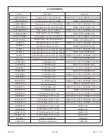
Before installing and securing the unit to the wall sleeve,
make sure that the proper louver kit is installed. Due the
high temperatures of the combustion products released from
the gas vent, MGE gas package units require the use of
either an aluminum louver kit or special MGE polypropylene
louver kit (see
ACCESSORIES
on page 17).
1. Make sure the gaskets attached to the sleeve are not
damaged.
2.
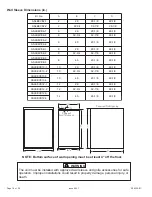
Verify divider panel is positioned properly. Figure 5 shows
the correct position for 60" and 64" tall units (flange
pointing up). For 58" tall units, the divider panel should
be positioned so the flange points down.
1.
Access vent pipe at the side of the unit that will face the
outdoors.
2.
The vent pipe and vent pipe extension is located to the
right of the outdoor fan (see Figure 3).
Vent Pipe Installation
Determining the length of the vent pipe extension is
dependent upon which wall sleeve accessory is installed at
the job site for each particular installation.
For proper operation, the vent length must be correct for
the installation. The unit may not operate correctly with
inadequate vent length.
CAUTION
Figure 3
Locating Vent Pipe and Extension
Mounting
Bracket
Vent Pipe
Outdoor Fan
Positioning Vent Pipe Extension
Figure 4
* The clearance holes are not marked on the actual
vent extension.
Outdoor Fan
0
Vent Extension
Clearance Holes*
Determining Hole Setting
Table 2
ASLEEVE12-1, 2, 3, 4
Hole
#
Wall Sleeve Used
Approximate
Length the Vent
Extends from
the Cabinet
ASLEEVE6-1, 2, 3, 4
ASLEEVE8-1, 2, 3, 4
ASLEEVE10-1, 2, 3, 4
ASLEEVE2-1,2
4
3
2
1
0
5.5 Inches
7.5 Inches
9.5 Inches
11.5 Inches
0 Inches


