Magic-Pak MGE4-09-18 Installation And Maintenance Instructions Manual Download Page 15

506326-01

Page 15  of  20

Issue 0941

Limit Control

A fixed temperature limit control is provided which will shut
off the gas to the burners if the unit is overheated for any
reason.  The control must not be adjusted or relocated.

Rollout Switch

If for any reason the exchanger were to become blocked,
there is a temperature sensitive switch located above the
burners that will turn off the burners.  After correcting the
problem, this switch must be manually reset by pressing the
button on top of it.
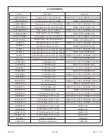
High Altitude

In both the United States and Canada, this unit is approved
for operation at altitudes from 0 to 4500 feet above sea level
without any required modifications.  From 4500 to 7500 feet,
the gas manifold pressure needs to be adjusted according
to the information shown in Table 5.  To adjust the manifold
pressure, refer to previous section 

Checking and Adjusting

Gas Input 

on page 13.  For installations above 7500 feet,

refer to the National Fuel Gas Code.

Installation and Operation in Extremely Cold Weather
Areas

In areas where extremely cold outdoor temperatures (below
– 20°F) can be expected, some additional installation and
operating precautions should be taken.  The following
precautions are designed to prevent possible vent system
ice blockage that could result in safety shutdown of the
burners:

1.

Adjust to the highest achievable temperature rise within
the rise and static pressure ranges specified on the rating
plate.  Depending on specific model, it may be possible
to change to a lower heating blower speed tap to get a
higher temperature rise.  This also increases comfort.

2.

Make sure there are no leaks of outside air into the return
air system.

3.

Keep the outside louver grille as free as possible of any
ice that may form and obstruct the flue outlet.

Summary of Contents for MGE4-09-18

Page 1: ...installation of this appliance must conform to the requirements of the National Fire ProtectionAssociation the National Electrical Code ANSI NFPA No 70 latest edition in the United States the Canadia...

Page 2: ...ice required Refer to Table 1 for the application limitations of the unit Location For information on wall sleeves and grille accessories see ACCESSORIES on page 17 The design is certified for thru th...

Page 3: ...on the unit and as tall as the unit IMPORTANT The unit must be installed with approved wall sleeve and grille accessories for safe operation Improper installa tions could result in property damage per...

Page 4: ...with appropriate wall sleeve accessories There is no minimum clearance required on locating the unit to an interior corner of a building If the unit is installed in a residential garage it must be loc...

Page 5: ...monoxide poisoning or death The following steps shall be followed for each appliance connected to the venting system being placed into operation while all other appliances connected to the common vent...

Page 6: ...all sleeve make sure that the proper louver kit is installed Due the high temperatures of the combustion products released from the gas vent MGE gas package units require the use of either an aluminum...

Page 7: ...unit to sleeve seal Caulk if needed Ductwork Ductwork should be designed and sized according to the methods in Manual Q of the Air Conditioning Contractors of America ACCA Check unit air supply outle...

Page 8: ...Low High MGE4 09 24 Low Medium Low Medium High Medium High High 650 630 610 580 550 500 470 435 390 370 670 640 575 520 460 750 690 645 575 490 795 740 680 616 535 945 900 860 810 775 1010 960 910 870...

Page 9: ...al Code CSA C22 2 Part 1 latest edition or local codes where they prevail Any alteration of internal wiring will void certification and warranty Units are factory wired for a 230 volt single phase pow...

Page 10: ...in the gas line outside the unit 5 above the floor or in accordance with any local codes The furnace must be isolated from the gas supply piping system by closing the individual manual shutoff valve d...

Page 11: ...dures Color coded insulated wires minimum 18AWG should be used to connect the thermostat to the unit The gas valve supplied with this furnace is rated at 1 2 psig maximum Any higher pressure may ruptu...

Page 12: ...er the pre purge time expires burners will light For Your Safety Read Before Lighting To Shut Down Unit 1 Turn off electrical power to unit 2 Depress and turn the gas valve knob to the OFF position se...

Page 13: ...r temporary or short periods of shutdown set the thermostat system switch to OFF For a prolonged period of shutdown set the thermostat system switch to OFF and turn off the electrical power supply and...

Page 14: ...ation Continuousoperationoftheairhandlingblowerwillbeobtained if the thermostat fan switch is set to ON With the thermostat fan switch set to AUTO the air handling blower will cycle corresponding with...

Page 15: ...5 To adjust the manifold pressure refer to previous section Checking andAdjusting Gas Input on page 13 For installations above 7500 feet refer to the National Fuel Gas Code Installation and Operation...

Page 16: ...tion control 3 Remove ignitor and flame sensor 4 Remove the four screws that mount the burner right side plate houses the ignitor flame sensing rod 5 Carefully remove the burner right side plate 6 Bur...

Page 17: ...2 6 Wall Sleeve Kit 6 Wall Sleeve Kit MGE4 10 30 MGE4 09 36 ASLEEVE8 1 ASLEEVE8 2 8 Wall Sleeve Kit 8 Wall Sleeve Kit MGE4 10 30 MGE4 09 36 ASLEEVE10 1 ASLEEVE10 2 10 Wall Sleeve Kit 10 Wall Sleeve Ki...

Page 18: ...V E E L S A 8 5 4 8 1 5 4 8 1 9 2 4 8 E V E E L S A 1 0 1 E V E E L S A 0 1 9 2 8 1 9 2 8 1 9 2 2 0 1 E V E E L S A 0 1 4 3 2 3 8 7 2 3 8 1 9 2 3 0 1 E V E E L S A 0 1 5 4 8 1 5 4 8 1 9 2 4 0 1 E V E...

Page 19: ...506326 01 Page 19 of 20 Issue 0941 Figure 10 Connection Diagram...

Page 20: ...Page 20 of 20 506326 01 Issue 0941 Figure 11 Schematic...

Reviews: